
Technical parameter
Nominal pressure: 1.6Mpa
Applicable temperature: 0 ~ 120 ¡æ
Applicable medium: water, oil and other non corrosive liquids
Flange standard: GB / t17241.6 GB / t9113 en1092
Test standard: GB / T 13927, API598
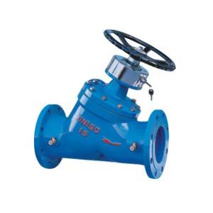
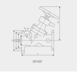
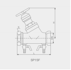
Drawing of SP45 / 15F locking balance valve
Typical installation diagram
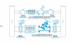
diagram
Material of main parts
| Part name | Valve body, valve cover | Stem | Valve disc | a seal |
| texture of material | Cast iron, ductile iron, carbon steel | stainless steel | Ductile iron | Rubber asbestos board |
Main connection dimensions
| SP45F | DN | 32 | 40 | 50 | 65 | 80 | 100 | 125 | 150 | 200 | 250 | 300 | 350 | SP15F | DN | 15 | 20 | 25 | 32 | 40 |
| L | 200 | 200 | 215 | 240 | 280 | 310 | 360 | 400 | 460 | 515 | 585 | 700 | ZG | 1/2” | 3/4” | 1” | 5/4” | 3/2” | ||
| L | 100 | 115 | 124 | 140 | 160 | |||||||||||||||
| H | 230 | 242 | 250 | 260 | 329 | 340 | 424 | 454 | 517 | 573 | 617 | 705 | H | 128 | 128 | 130 | 150 | 187 |
