0102030405
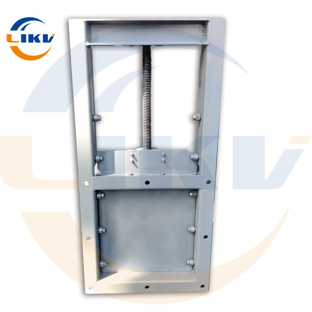
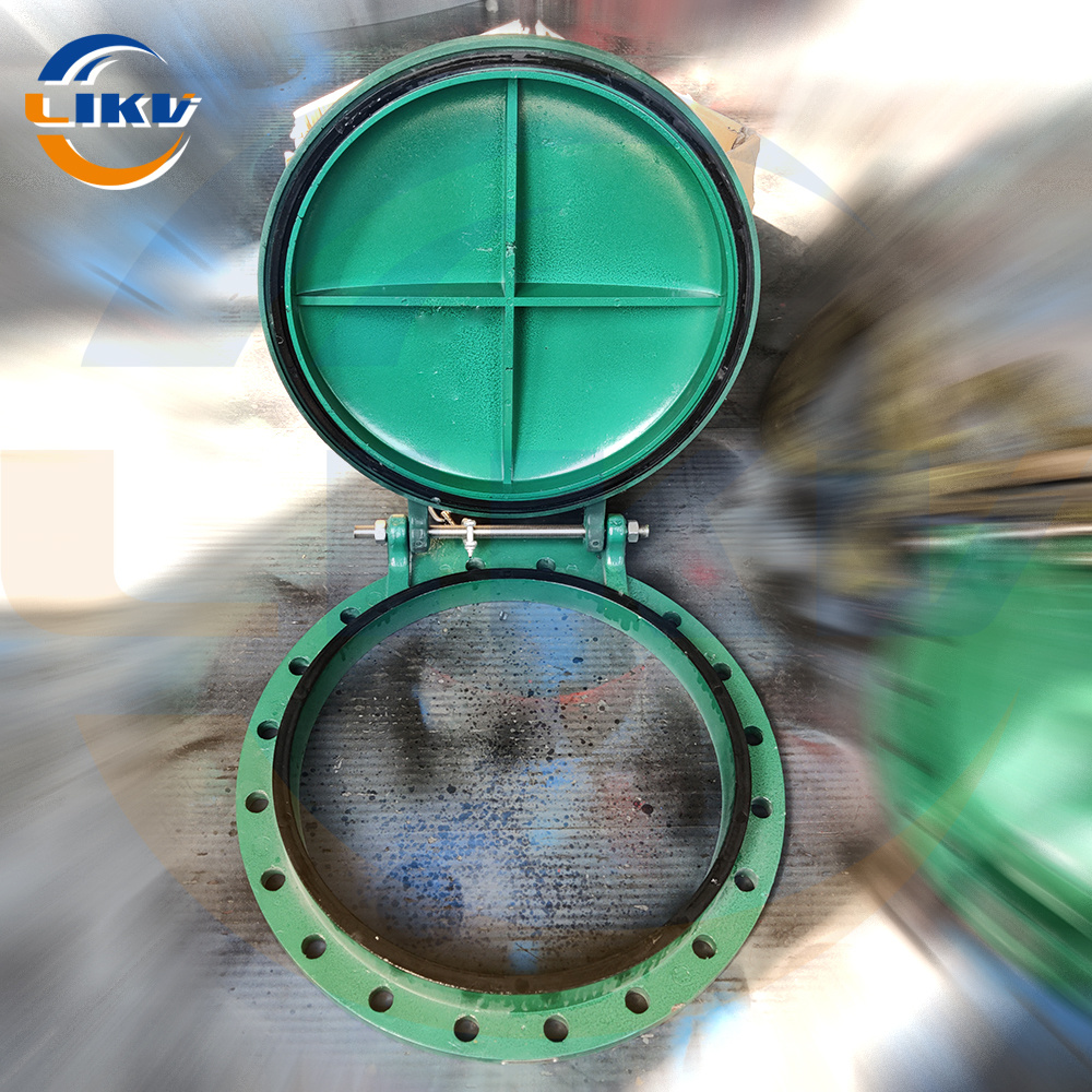
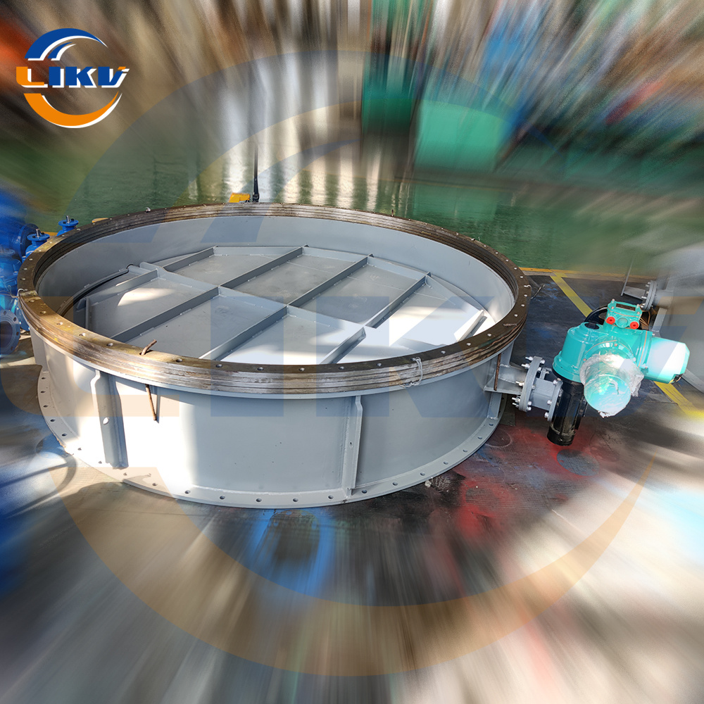
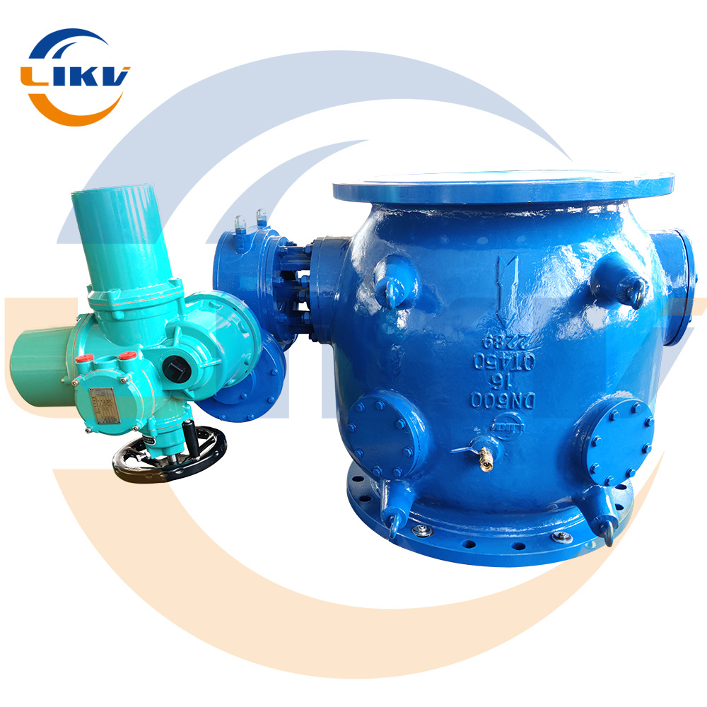
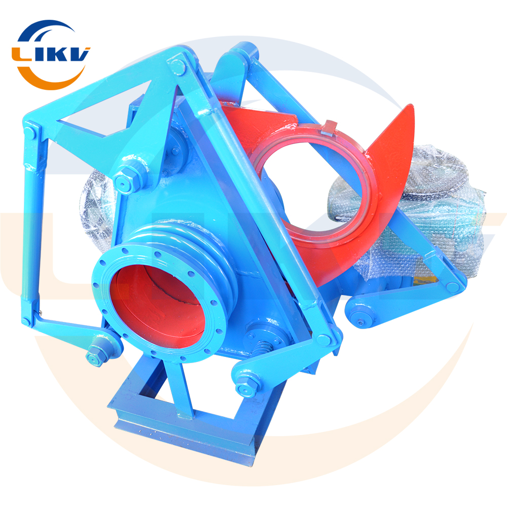
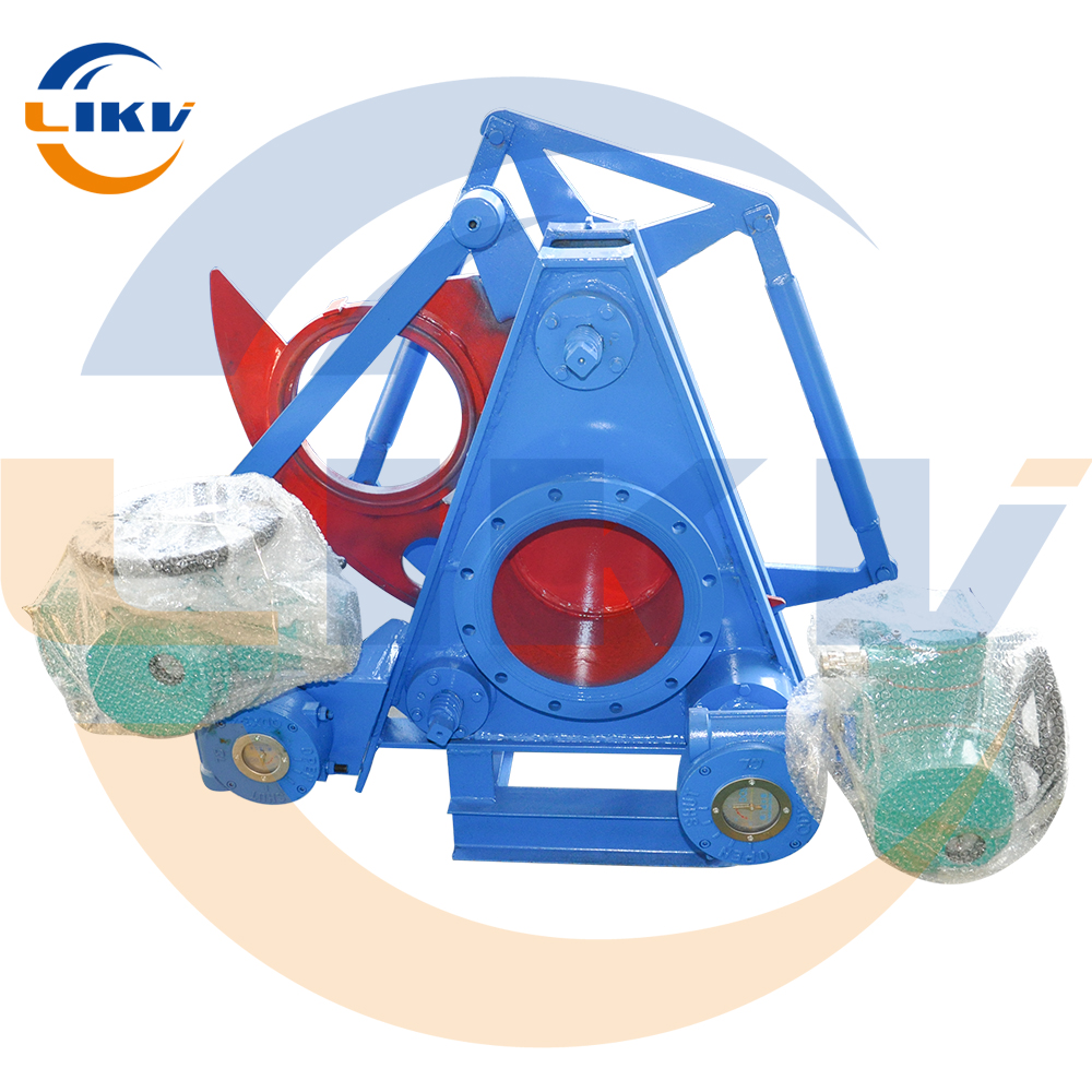
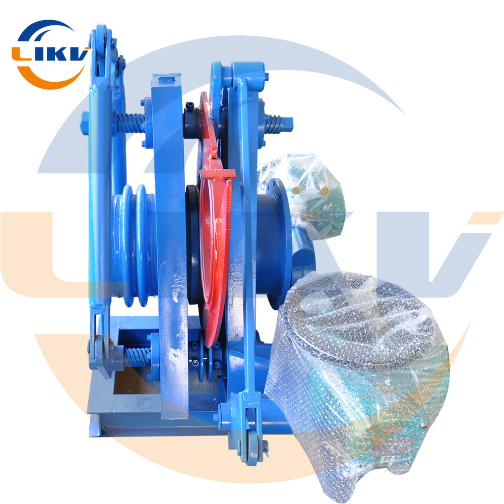
Carbon steel electric manual blind valve F9T43X-0.5 is suitable for gas power plant smoke fan-push rod type electric glasses valve, specification DN300-DN2000
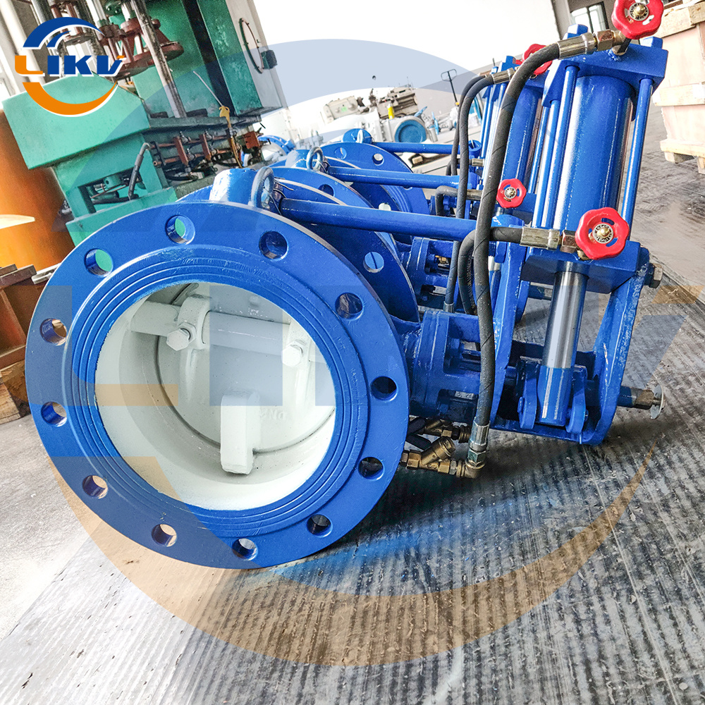
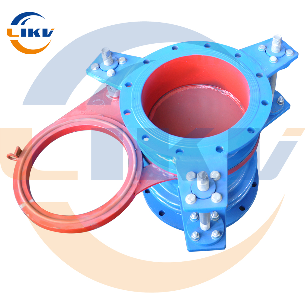
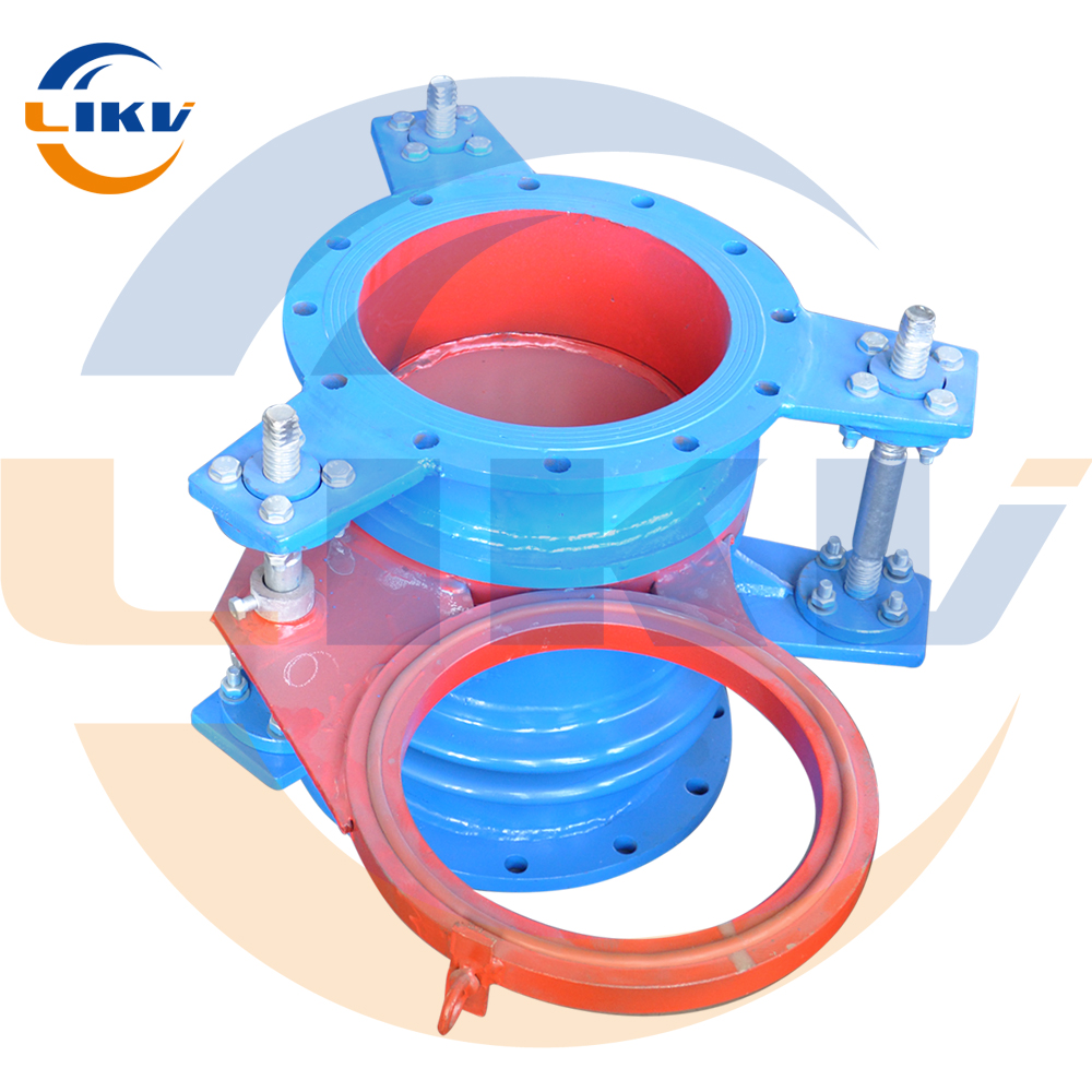
Blind Plate Valve Usage Instructions This series of radial blind plate valves is mainly composed of the left valve body, right valve body, valve plate, rubber sealing ring, screw-nut pair, electric, pneumatic or hydraulic actuating mechanism. It also consists of a base and support column to form a rigid structure. During field installation, it is strictly prohibited to remove the base, support column and other accessories. The valve is equipped with opening and closing push rod and flap push rod. The opening and closing push rod drives the screw-nut pair through the linkage mechanism to complete the clamping and unclamping action of the valve body. The flap push rod drives the valve plate to complete the switching action of the through hole and blind hole. The stroke of the opening and closing push rod and the flap push rod is controlled by the travel control switch on the push rod. The valve is equipped with a stainless steel bellows compensator, which is only responsible for the opening and closing of the valve and is not allowed to replace the compensator that should be installed in the pipeline. A separate compensator should be installed in the pipeline, otherwise, the external force generated by the thermal expansion and contraction or stretching and twisting of the pipeline will be transmitted to this valve, resulting in pushing, pulling, twisting and other actions on the valve, thus affecting the working performance of the valve. After installation of this valve, please loosen or remove the three fixing bolts on the compensator to avoid affecting the compensator's extension performance during operation. After installation of this valve, commissioning should be carried out. Firstly, use manual to loosen the opening and closing push rod to half open state, then connect the motor power cord and travel switch control wire, after energization, check whether the motor rotates forwards or backwards and whether the travel switch acts accurately. After energization is correct, respectively test whether the valve is in loose position and closed position when the travel switch acts accurately. If they are not synchronous, adjustment should be made. After adjustment for 2-3 times, loosen the valve and then adjust according to the same steps as above for the flap push rod (it is recommended that one person controls the travel switch at the valve site and one person controls the button at the controller site during adjustment of the valve, so that they can cooperate with each other to adjust and in case of failure, cut off the power in time, remove the fault and then carry out commissioning again). The medium inlet of this valve is on the side without compensator, and the medium outlet is on the side with compensator; attention should be paid to it during installation. This valve is an open type valve, during opening and closing process, there will be media leakage, safety measures must be taken during operation. It is recommended to install a tight butterfly valve before and after this valve to reduce media leakage during opening and closing process. During use of this valve, it should adhere to the principles of regular inspection, adjustment, lubrication and maintenance to prolong its service life and maintain good working condition. Special Note: The chassis bracket provided with this valve is prohibited from being disassembled or removed during installation, and a working platform must be added under the bracket to fix the chassis during installation, otherwise it will destroy the overall performance of the valve and cause it cannot be used normally, serious cases can even lead to scrapping of the entire valve. Main Performance Specifications Product Model F643X-0.5 F743X-0.5 F9T43X-0.5 Nominal Diameter DN 300-1200 300-2000 300-2000 Nominal Pressure MPa 0.05 0.05 0.05 Sealing Test Pressure MPa 0.055 0.055 0.055 Strength Test Pressure MPa 0.075 0.075 0.075 Actuating Source Compressed air 0.4-0.6MPa Pressure oil 4-6MPa 3-phase 380V50HZ Operating Temperature℃ -20℃-120℃ -20℃-200℃ Opening/Closing Time/Seconds ≤60 seconds
