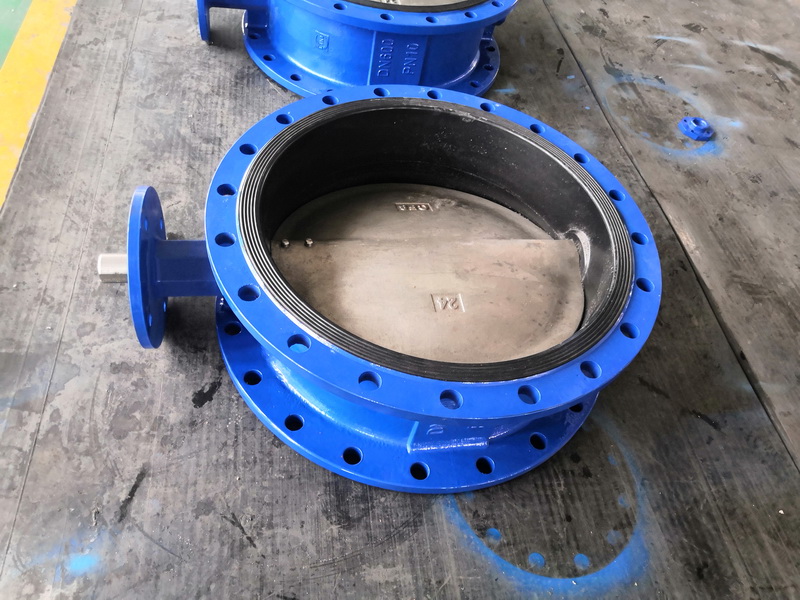
General valve structure and application – check valve, pressure regulating valve, valve gate valve Common sense: pilot safety valve installation specification and principle
Check valve check valve is to remotely switch and close the disc with the help of the medium’s own liquidity, used to avoid the reverse flow of the medium gate valve.
Check valve
Check valve is to remotely switch and close the disc with the help of the medium’s own liquidity, used to avoid the reverse flow of the medium gate valve.
One, the type of check valve
Two, the structure of the check valve
1. Swing check valve
Pressure loss is small, sealing is not as good as the lifting mechanism. It is not suitable for pulsating flow where low flow velocity and liquidity have not changed for a long time.
(a) Double disc type: medium level specification.
(b) Double flap type: relatively large size (DN≤600).
(c) Multi-disc type: lower water hammer, no surface damage, small caliber (DN600).
1. Oil circuit plate 2. Baffle 3. Single flow valve 4. Disc 5. Intake valve
2, lift type check valve
(a) directly connected regulating check valve
(b) column type regulating check valve
Pump bottom valve pump suction channel setting. Avoid countercurrent, conducive to start the pump.
Three, the characteristics of the check valve
The lift check valve has the same oil path plate as the stop valve (can be universal with the stop valve), so its fluid resistance coefficient is relatively large.
Swing check valve, disc tightly around the outer shaft sleeve of the high pressure gate valve, is widely used.
Butterfly check disc tightly around the shaft sleeve in the high pressure gate valve. Simple structure, only installed in the level pipe, airtight is weak.
Pressure regulating valve
Pressure reducing valve depends on the valve disc, torsion spring, piston rod and other photoresistor to change the gap between the disc and the valve block, the pressure at the inlet is reduced to the pressure at the outlet, and with the help of the medium’s own energy, the pressure at the inlet and outlet is automatically maintained.
First, the type of pressure regulating valve
(1) According to the mode of action:
(a) Direct action: complete control of disc fitness exercise with inlet and outlet pressure change;
(b) Pilot type: It is composed of main valve and pilot valve, and the change of inlet and outlet pressure controls the position of the main valve according to the enlargement of the pilot valve.
(2) By structure type:
(a) Plastic film type
(b) torsion spring plastic film type
(c) Piston machine
(d) Bellows type
(e) Financial leverage
Two, the structure of the universal pressure regulating valve
(1) torsion spring plastic film type
1 adjusting screw 2 adjusting torsion spring 3 single flow valve 4 plastic film 5 oil circuit plate 6. disc
(2) piston machine
1 adjusting screw 2 adjusting torsion spring 3 cap cover 4 deputy high pressure gate valve 5 auxiliary valve disc 6. Single flow valve 7. Piston rod 8. Disc 9. Main disc 10. Main seat
Three, pressure regulating valve performance
(1) Static characteristic error:
Flow coefficient error: indicates outlet pressure fluctuation caused by flow change.
Pressure characteristic error: indicates that the outlet pressure fluctuation is caused by the change of pressure.
(2) insensitivity error:
When the inlet and outlet pressure changes within a certain range, it can not cause the pressure regulating valve to change the operation category. It shows that the pressure regulating valve is not sensitive.
valve
Safety valve is an automatic valve, it will not rely on all external force, the use of medium pressure to discharge a certain amount of liquid, in order to avoid the system of pressure beyond the set standard value. When the pressure is restored to the normal standard value, the gate valve is automatically closed again to prevent the medium from discharging again.
One, the type of valve
Two, the valve structure
Spring type valve:
Pulse valve
Structure has a main valve, auxiliary valve. The auxiliary valve is a minimal immediate load valve connected to the main valve. When the system software overpressure, auxiliary valve first open, exhaust medium. Suitable for small caliber, large horsepower and high pressure system.
1 pilot valve 2. Main valve 3. Park top brake chamber 4. Piston seal ring 5. High pressure gate valve 6. Pressure sensor nozzle
Three, the selection of valves
(1) Fast reaction speed;
(2) Having the required discharge pressure;
(3) Ensure compressive strength, tightness and reliability in use;
(4) Allowable errors and specified values of postural characteristics.
Pilot type safety valve is a kind of safety protection valve, it opens and closes parts under the action of external force in the normally open and normally closed situation, when the medium pressure in the equipment and pipeline rises, beyond the standard value automatically opened, can be discharged to the system software to prevent the medium pressure in the pipeline or equipment beyond the range of standard value. Pilot safety valve used in natural gas, liquefied natural gas and chemical plant pressure vessels equipment and industrial pipelines, with explosion-proof safety, anti-static, reliable sealing, fast opening and closing and large displacement of the highlighted advantages.
Pilot type safety valve is a kind of safety protection valve, it opens and closes under the action of external force in the normally open and normally closed situation, when the medium pressure in the equipment and pipeline rises, beyond the standard value automatically opened, can be discharged to the system software to prevent the medium pressure in the pipeline or equipment beyond the range of standard value. Pilot safety valve *** is used in natural gas, liquefied natural gas and chemical plant pressure vessels equipment and industrial pipelines, with explosion-proof safety, anti-static, reliable sealing, fast opening and closing and large displacement of the highlighted advantages.
Structural characteristics of pilot safety valve
Pilot type safety valve by the main valve, pilot valve, relief valve, connecting head and hose. Under conventional conditions, the overall medium pressure is applied to both the lower and upper parts of the main disc.
Because the total area of the brake chamber medium efficacy above the main disc is greater than the total area of the medium efficacy below the main disc, under the influence of pressure difference, the main disc is in the shutdown state. With the rise of pipeline medium pressure, the seal specific pressure obtained will be accompanied by an increase, which is exactly the opposite of the torsion spring immediate load valve, that is, the greater the medium pressure, the more reliable the seal. When the pipeline medium pressure is abnormal and reaches or exceeds the setting pressure, the valve flap of the pilot valve (FIG. 2) opens quickly, and the medium in the air chamber above the main valve flap is discharged rapidly according to the exhaust pipe connector of the pilot valve. Under the influence of the super strong medium pressure below, the main valve flap opens instantaneously, and the medium is discharged rapidly from the outlet of the main valve. The medium pressure in the pipeline is restored to normal working pressure to ensure the safety of the system software.
When the pipeline medium pressure drops to about 90% of the valve setting pressure set by the system software, the valve disc on the pilot valve is closed, and the pipeline medium also enters the brake chamber above the main valve disc through the pilot valve. Under the influence of pressure difference, the main valve is closed to ensure full normal operation.
Principle of pilot safety valve
The pilot valve is composed of oil circuit plate, lower valve disc, small chain, vent joint, upper valve disc, torsion spring and drain valve.
Under normal conditions, the pilot valve upper disc in the off state, pilot valve lower disc in the open condition. The pipeline medium enters the air room above the main valve disc according to the lower valve disc, so that the main valve disc is closed. When the pipeline medium pressure is abnormal and reaches or exceeds the set whole strength, the lower valve disc of the pilot valve is closed under the influence of the medium pressure, and the pipeline medium is disconnected into the safety channel above the main valve disc. At the same time, the valve disc of the pilot valve is pushed up by the small chain, that is, the pilot valve is opened, and the air chamber medium above the main valve disc is quickly discharged according to the exhaust pipe connector. Under the super strong influence of the medium pressure below the main valve disc, it opens instantly, and the pipeline medium is discharged from the outlet of the main valve rapidly, so that the pipeline medium pressure is restored to the normal working pressure, to ensure the safety of the system. When the pipeline pressure drops to about 90% of the setting pressure set by the system software, the upper valve disc of the pilot valve is closed under the action of the spring. At the same time, the lower valve disc of the pilot valve is pushed open by the small chain. The pipeline medium enters the brake chamber above the main valve disc according to the lower valve disc, and the main valve disc is closed under the influence of the pressure difference, ensuring the normal use of the system software.
If it is found that the pipeline medium pressure is abnormal, and the pilot valve failure can not be opened, the pilot valve in the relief valve, release the main valve disc above the air chamber medium, so that the main valve disc open, release the media in the pipeline abnormal pressure, to ensure the safety of the system.
Installation specification for pilot operated safety valves
(l) The heating furnace with rated evaporation capacity over 0.5t/h shall be equipped with at least 2 pilot safety valves: The heating furnace with rated evaporation capacity less than or equal to 0.5t/h shall be equipped with at least one valve. Rational boiler energy saver inlet and outlet, steam heating surface inlet and outlet must be arranged pilot safety valve.
(2) pilot safety valve should be vertically installed in the pot, pot cylinder relatively high position. Between the valve and the furnace body or drum, the steam outlet pipe and gate valve shall not be equipped.
(3) The pilot type safety valve needs to avoid the weight type autonomous moving device and limit the financial lever derailed behavior guide frame, spring type safety valve needs to improve the hand and prevent random screw adjustment device.
(4) For gas boilers with rated vapor pressure less than or equal to 3.82MPa, the throat diameter of pilot safety valve should not be less than 25mm: For gas boilers with rated vapor pressure more than 3.82MPa, the valve throat diameter should not be less than 20mm.
(5) pilot type safety valve and boiler rubber tube, the section shall not be less than the entrance section of the valve. If several valves are placed together on a tube collar immediately connected with the furnace body, the channel section of the tube collar should not be more than 1.25 times the total valve exhaust area.
(6) pilot type safety valve should generally be placed exhaust pipe, exhaust pipe should direct safety address, and have sufficient section to ensure smooth exhaust steam. The bottom end of the exhaust pipe of the valve should be filled with cavities to pretend that there is a drain pipe received in a safe place, and the gate valve can not be placed on the exhaust pipe and drain pipe.
Post time: Mar-18-2023


