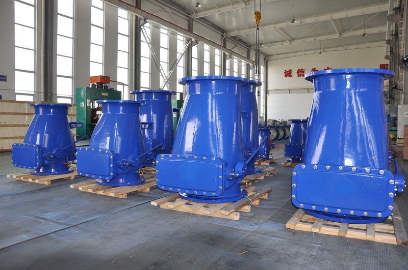
Application scope and technical requirements of power station valves (IV)
Application of electric valve, is to reduce the workers labor intensity and necessary in bad working environment, electric valve consists of motor, gear box and the body, usually in the frequent work due to factors such as vibration, temperature, sealing aging often various oil leakage problem, gear box leakage serious environmental pollution not only there are some potential safety hazard. The safety accident lessons caused by the “running, running, dripping and leaking” of the equipment are also constantly paid attention to in the equipment management work. The gear box leakage oil, due to the equipment structure, the use of the environment, continuous work and other conditions, in the traditional with the replacement of parts, with the replacement of sealing measures
Causes and analysis of oil leakage in electric valve gear box
Application of electric valve, is to reduce the workers labor intensity and necessary in bad working environment, electric valve consists of motor, gear box and the body, usually in the frequent work due to factors such as vibration, temperature, sealing aging often various oil leakage problem, gear box leakage serious environmental pollution not only there are some potential safety hazard. The safety accident lessons caused by the “running, running, dripping and leaking” of the equipment are also constantly paid attention to in the equipment management work. Due to the limitation of equipment structure, operating environment and continuous working conditions, the oil leakage of gear box is difficult to be fast and effective in the traditional solutions of replacing parts and sealing.
The total installed capacity of Huaneng Power Plant is 2060MW, and the expansion conditions of 2×1000MW units are reserved for the third phase. The 2×350MW unit of the first phase project is the imported unit designed jointly by China and foreign countries. The main equipment selection is advanced, the arrangement is compact, the unit has high economy, and the protection function is perfect. It is a modern thermal power plant with a high degree of automation in China. The second phase of the project is 2×680MW domestic supercritical coal-fired units, simultaneous construction of seawater flue gas desulfurization device.
Field application case of Carbon nanopolymer materials in treating leakage of gear casing from Soley Industry
The onsite operation procedure is as follows:
1, clean up the oil leakage parts, polish around the leakage parts, so that it shows the metal primary color, bolt parts are also surface treatment;
2, clean up, surface treatment requirements clean, dry, solid, rough;
3. Blend SD2240 material to seal up the leaking parts in a small range until there is no leakage;
4. After the surface of the material is cured, the material is covered with SD7111C again. The material is cured and repaired.
Application scope and technical requirements of power station valve (iv) The maximum service temperature of the bearing parts of the shell does not consider the allowable temperature deviation of the boiler during normal operation, and the deviation value shall be in accordance with the provisions of SDGJ6-1990. Attention should be paid to graphitization of metallic materials under the following conditions: Chromium-aluminum steels (up to 0.6%) are used for a long time above approximately 525℃. The valve body and pipe connection weld is field weld, its end groove is pre-processed by the valve manufacturing department. The butt welding method of valve body channel end should be hand arc welding, hydrogen arc welding plus hand arc welding or other welding methods qualified by the process evaluation.
Connection: Application scope and technical requirements of power station valves (III)
Appendix c
(Normative Appendix)
Maximum service temperature of shell bearing material
C.1 When selecting materials for bearing parts of the shell, the maximum service temperature shall not exceed the provisions in Table C.1.
Table C.1 Maximum service temperature of shell bearing material
C.2 The maximum operating temperature of the bearing parts of the shell does not consider the allowable temperature deviation during normal operation of the boiler, and the deviation value shall be in accordance with the provisions of SDGJ6-1990.
C.3 Possible graphitization of metallic materials should be noted in the following cases:
A) Carbon steel is used for a long time above about 425℃.
B) Carbon aluminum steel is used for a long time at about 470℃.
C) Chromium-aluminum steel (containing less than 0.6%) is used for a long time at about 525℃.
C.4 Attention should be paid to possible peroxidation (oxidation of skin) in the following cases:
A) 1Cr-0.5Mo steel, 1.25Cr-0.5Mo steel, 2.25Cr-1Mo steel and 3Cr-1Mo steel above 565℃;
B) 5Cr-0.5Mo steel above 595℃.
Appendix D
(Informative Appendix)
Hardfacing material and hardness of valve sealing surface
Table D.1 provides guidelines for designers on the selection of surfacing materials and surfacing hardness for valve sealing surfaces.
Table D.1 Hardfacing material and hardfacing library for valve sealing surface
Appendix E
(Informative Appendix)
Butt weld groove type of valve body channel end
E.1 Butt weld groove type of various valves with butt pipe wall thickness δ20mm is shown in Figure E.1
E.2 butt weld groove of valves with pipe wall thickness of 20mm ≤δ≤40mm is shown in figure e. 2
E.3 Butt weld groove type of various valves with butt pipe wall thickness δ40mm is shown in Figure E.3
E.4 The dimensions of D1, D2 and D3 in Figure E1, Figure E.2 and Figure E.3 are not given, which are determined by the design drawing. D1 is equal to the basic size of the pipe inner diameter, and D: can be calculated from the following formula:
Type:
Outside diameter of DW-1 piping:
A – The added value shall be determined by the designer with reference to Table E.1.
Table E.1 Added value of butt weld groove dimension D2
E.5 When the connection weld between valve body and pipe is field weld, the end groove shall be pre-processed by the valve manufacturing department.
E.6 Welding method of butt weld of valve body channel end should adopt hand arc welding, hydrogen arc welding plus hand arc welding or other welding method qualified by process evaluation.
Note 1: When Lo≥1.5δ, the Angle can be chamfered at Lo=1.5δ as shown in the 45° slope.
Note 2: The cast steel valve body groove with nominal diameter DN≥150mm shall be L1=40mm for radiographic inspection, L1=12mm for other cases
FIG. E.1 V-shaped groove type
Note 1: When Lo≥1.5δ, the Angle can be chamfered at Lo=1.5δ as shown in the 45° slope.
Note 2: The cast steel valve body groove with nominal diameter DN≥150mm shall be L1=40mm for radiographic inspection, L1=12mm for other cases
FIG. E.2 U-shaped groove type
Figure E.3 U(1) groove type
Appendix F
(Informative Appendix)
Metal nameplate
F.1 Table F.1 shows the contents of metal nameplates on globe valves, check valves, gate valves, throttle valves and plug valves.
Table F.1 Metal nameplates for globe valves, check valves, gate valves, throttle valves, plug valves, etc
F.2 Table F.2 shows the content of the metal nameplate of the regulator
Table F.2 Metal content of regulator
F.3 Table F.3 shows the content of the safety valve metal nameplate
Table F.3 Metal nameplate of safety valve
F.4 Table F.4 shows the content of the metal nameplate of the pressure reducing valve
Table F.4 Metal nameplate of the pressure reducing valve
F.5 Table F.5 shows the metal nameplate of the temperature and pressure reducing valve.
Table F.5 Metal nameplate of the temperature and pressure reducing valve
Post time: Jul-26-2022


