
Selection and setting of valve part of the valve electric device model preparation method
1. When the pipe diameter is not larger than 50mm, globe valve should be used; when the pipe diameter is larger than 50mm, gate valve and butterfly valve should be used; 2. When the flow rate needs to be adjusted, the water pressure should be adjusted by regulating valve and globe valve
Principle of selection of valves for use in water supply pipelines
1. When the pipe diameter is less than 50mm, globe valve should be used. When the pipe diameter is greater than 50mm, gate valve and butterfly valve should be used
2, need to adjust the flow, water pressure should use the regulating valve, stop valve
3. Gate valves should be used where water flow resistance is small (such as water pump suction pipe)
4. Gate valve and butterfly valve shall be used on the pipe section where water flow is two-way, and stop valve shall not be used
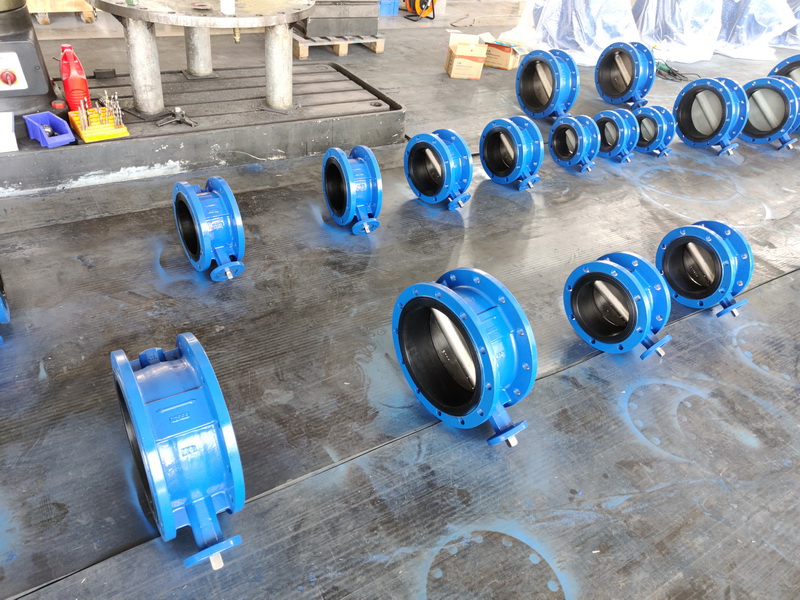
5. Butterfly valve and ball valve should be used for small installation space
6. In the pipe section that is often opened and closed, stop valve should be used
7, the large-caliber water pump outlet pipe should use multi-function valve
(2) The position of the valve on the water supply pipeline
1. The water supply pipeline of residential district is from the leading pipe section of municipal water supply pipeline
2. The nodes of outdoor circular pipe network in residential areas should be set according to the separation requirements. If the annular pipe section is too long, segmented valves should be set
3, from the main water supply pipe in residential areas from the beginning of the branch pipe or the beginning of the household pipe
4. Indoor pipe, water meter and each branch riser (bottom of riser, upper and lower part of vertical ring pipe network riser)
5, ring pipe network branch pipe, connecting pipe through the branch pipe network
6, indoor water supply pipeline to households, public toilets, etc. from the start of the water distribution pipe, water distribution branch pipe water distribution points in 3 and more than 3 set
7, water pump outlet pipe, self-irrigation pump suction pump
8. Water tank inlet and outlet pipes and drainage pipes
9, equipment (such as heater, cooling tower, etc.) water refill pipe
10, sanitary appliances (such as large, urinal, wash basin, shower, etc.) of the distribution pipe
11, some accessories, such as automatic exhaust valve, pressure relief valve, water hammer eliminator, pressure gauge, sprinkler bolt, pressure reducing valve and reverse flow prevention device before and after
12. The drainage valve should be set at the lower part of the water supply network
(three) check valve selection
Check valves should be selected according to the installation position, the water pressure before the valve, the sealing performance requirements after closing and the size of the water hammer triggered when closing, etc. :
1. When the water pressure before the valve is small, swing type, ball type and shuttle check valve should be selected
2. When the airtight performance after closing is strictly required, the check valve with closing spring should be selected
3. When the water hammer is required to be weakened and closed, it is advisable to choose the fast closing silencing check valve or the slow closing check valve with damping device
4, check valve break or spool, should be able to close under the action of gravity or spring force
(4) Check valves shall be installed in water supply pipelines
Into the pipe; On the intake pipe of closed water heater or water equipment; On the water pump outlet pipe; On the outlet pipe section of the water tank, water tower and upland pool of the same pipe.
Note: check valves are not required for pipe sections with pipe backflow preventers.
(5) The position of the exhaust device for the water supply pipeline
1, intermittent use of water supply pipe network, the end of the pipe network and the higher point should be set with automatic exhaust valve
2. Automatic exhaust valve or manual valve has been set at the peak point of the pipe section with obvious undulating air accumulation in the water supply network
3, air pressure water supply device, when the use of automatic air filling type air pressure water tank, the comparison of the water distribution network should be equipped with automatic exhaust valve
This standard applies to motor drive, electrical contact control, single speed gate valve, globe valve, drill I valve, diaphragm valve, ball valve, plug valve, butterfly valve and other valve electric devices (hereinafter referred to as electric devices). The following beach contains provisions which, by reference in this international standard, constitute provisions of this international standard. The editions shown are valid at the time of publication of this standard. All standards are subject to revision and parties using this standard should explore the possibility of using *** versions of the following standards.
1 scope
This standard specifies the method of compiling the type of valve electric device.
This standard applies to motor drive, electrical contact control, single speed gate valve, globe valve, throttle valve, diaphragm valve, ball valve, plug valve, butterfly valve and other valve electric devices (hereinafter referred to as electric devices).
2 Reference Standards
The following beach contains provisions which, by reference in this international standard, constitute provisions of this international standard. The editions shown are valid at the time of publication of this standard. All standards are subject to revision and parties using this standard should explore the possibility of using *** versions of the following standards.
GB 4831-84 Specification method for motor products
3 Model Establishment
3. 1 type
Electric device divided into Z, Q double profit type. Type Z means multi-rotary electric device 8 suitable for gate valve, globe valve, diaphragm valve, etc. Type Q represents part of the rotary electric device, suitable for ball valves, plug valves, butterfly valves, etc.
3. 2 Model representation method
3. 2. 1 Model representation method of multi-rotary electric device
3. 2. 2 Part rotary electric device model representation method
Table 1 Protection type code
3. The model is an example
For gate valves, globe valves, throttle valves and diaphragm valves, relatively large control rotation of 1800 Nm, rated output shaft speed of 18 r/min, output shaft relatively large turning number of 80, explosion-proof electric device, model is expressed as:
Z 180-18/80 B
For ball valves, plug valves and butterfly valves, the larger control system is 1200 Nm, the rated speed of the output shaft is 2 r/min, the general electric device, the model is shown as:
Q120-2
Post time: Jun-22-2022


