
Valve interior material use temperature valve picture, structure diagram
Valve inner material service temperature: for example, type 304 stainless steel type 316 stainless steel bronze Incor nickel alloy K manganese Nael alloy Manganese Nael alloy Hasloy alloy Hasloy alloy material service temperature.
Service temperature of valve inner material
Material lower limit /° C lower limit /°F upper limit /° C upper limit /°F Type 304 stainless steel -268-450316600316 type stainless steel -268-450316600 bronze -273-460232450 Inkor nickel alloy -240-4006491200K Manganese Nael alloy -240-400482900 Manganese Nael alloy – Hasloy alloy B-371700 Hasloy alloy C-5381000 titanium alloy -316600 nickel base alloy -198-32531660020 alloy -45-50316600416 type stainless steel 40RC-29-20427800440 type stainless steel 60RC-29-2042780017-4PH-40-404278006 Alloy (Co-CR) -273-4608161500 electroless nickel plating -268-450427800 Chrome plating -273-460316600 nitrile rubber -40-4093200 Fluorine rubber -23-10204400 Teflon -268-450232450 nylon -73-1009320 0 polyethylene -73-10093200 Neoprene -40-4082180 valve picture, structure diagram
Introduction to valve picture and structure drawing:
There are many kinds of valves, and their structure is also quite complex, so how should we understand the valve in the ordinary use process? I took a detailed below to show the ball valve structure, the check valve pictures gate valves, globe valves details figure, anatomy and regulating valve drawings, and mark the parts name for each valve, also do the simple structure principle is introduced, its valves are all made of original images, hope to help more and more users really understand valve structure.
Floating ball valve structure principle:
Floating ball valve structure through full size, open-close part O the ball, or two-way sealed and direction of the ball valve closing medium to tetragonal have sealed, no fixed at the bottom of the shaft, automatic pressure ball seat seal, is called the floating ball valve, the following is a minister card Q41F – 16 p stainless steel floating ball valve structure, for the masses of users to enjoy.
Floating ball valve structure diagram:
Three-way ball valve structure principle:
Three-way ball valve structure is divided into L type and T type, L type in the pipeline mainly plays a shunting role, generally for the middle inlet, both ends for the outlet. T type confluence type in the pipeline mainly plays the role of confluence, commonly used flow direction is generally left into the right side or middle into the right side, Gu called two into a three-way ball valve. The FOLLOWING IS THE LEGEND OF THE L-SHAPED BALL VALVE. For MORE FLOW diagram, TECHNICAL parameters, samples and prices, please contact the staff of the company.
Three-way ball valve structure diagram:
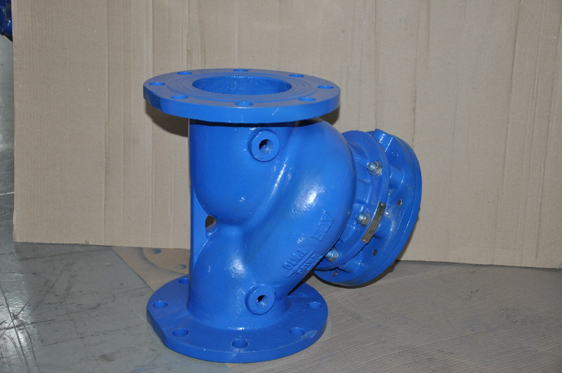
Swing check valve structure principle:
Swing check valve is also known as the one-way valve, the structure of the single flap swing type, the positive flow is the baffle swing, counter flow when the baffle down pressure valve cover, so that the reverse medium is blocked in the valve, can also be called reverse flow valve, check valve, etc. Swing check valve belongs to the automatic valve class, the function principle is to only allow the medium to flow in one direction, to prevent the medium countercurrent on the front-end pump or other equipment damage.
The following is the picture of Taichen H44H swing check valve for your reference.
Swing check valve structure drawing:
Manual stop valve structure principle:
Manual stop valve structure using low into high form, the flow resistance is larger than other valves, but the sealing form is better than other valves, Taichen brand manual stop valve using conical spool, can be used for throttling, cut-off, or adjust the working condition. Manual cut-off valve opening and closing parts for the valve disc, a forced sealing valve, the valve disc along the center line of the seat for linear movement.
The following is the detail diagram of J41H manual globe valve, which introduces the name of each component in detail, so as to provide new and old customers with a more convenient understanding of the structure principle of globe valve.
Manual stop valve structure diagram:
Manual gate valve structure principle:
Manual gate valve opening and closing parts for the gate plate, the gate plate and fluid in the vertical direction to do lifting movement, the gate valve seal by the valve seat and gate plate contact, the gate plate and seat seal welding metal materials, with wear resistance, high temperature resistance and other advantages. Ram can be divided into rigid disc and flexible disc, choose according to user different working condition, but the forms are not suitable for all types of gate structure adjust medium, only the user switch is used, the following is a minister Z41H manual gate valves anatomy, wire-cutting after can see internal structure, can be used for teaching, exhibition, welcome each big manufacturer for our company.
Manual gate valve structure diagram:
Pneumatic control valve structure principle:
Pneumatic control valve is a valve that automatically adjusts the pressure, flow and temperature of the medium. The structure is composed of pneumatic thin film actuator, regulating valve, positioner and other accessories. Pneumatic control valve works with compressed air as the power, pneumatic actuator as the driving mode, the regulating valve as the flow area of the throttling medium, with the locator to receive the analog signal amount of 4-20 mA, to achieve the fine control of the pipeline medium flow, pressure and other parameters. The following is the drawing of Taichen ZXP pneumatic film single seat regulating valve. The detailed dynamic diagram and working principle of pneumatic regulating valve can be viewed in the knowledge of regulating valve in the station, or ask for it from the staff.
Pneumatic control valve structure diagram:
Many different kinds of regulating valve, pneumatic control valve, electric valve, self regulating valve, etc., pneumatic control valve need to source and sensor, but failure can be spring return pneumatic actuators on or off, suitable for the occasion of the large range of pressure difference, electric regulating valve work by electric actuator receives the signal source, according to the signal control valve opening, It has the advantage of high precision adjustment, but the disadvantage is that the fault stays in place. Self-regulating valve work without exogenous, energy saving and environmental protection, but also can be used to adjust the temperature, flow, pressure and other occasions, the disadvantage is that the leakage than pneumatic and electric regulating valve. The following is the dynamic diagram of the pneumatic control valve for reference.
Post time: Aug-20-2022


