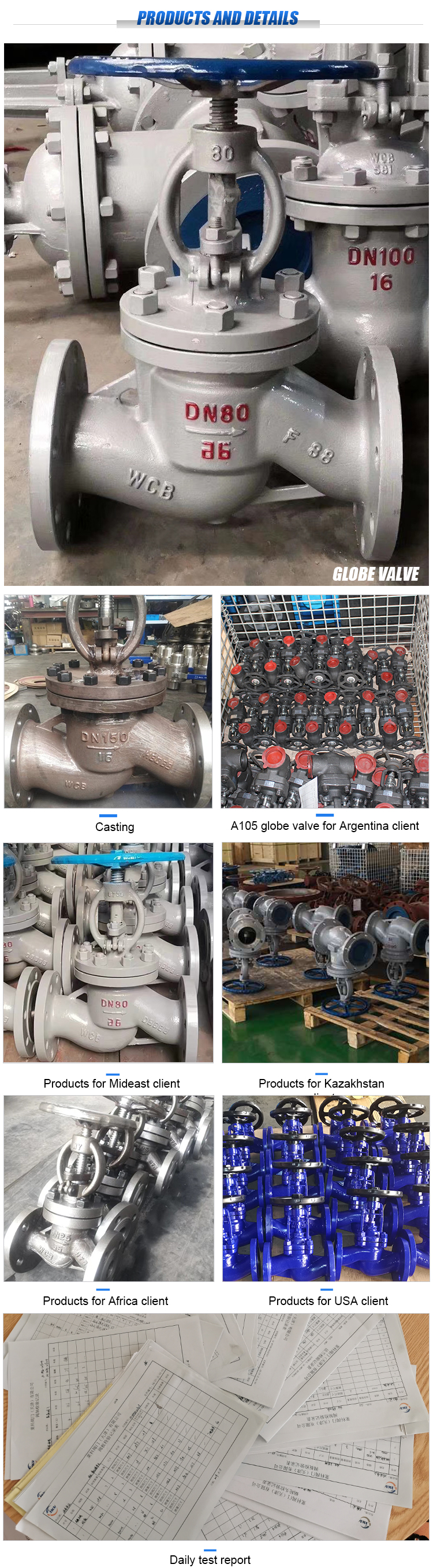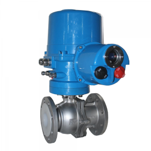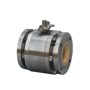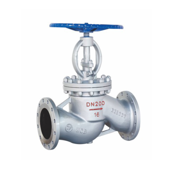
Features of J41H / y flange globe valve
1. The product has reasonable structure, reliable sealing, excellent performance and beautiful appearance;
2. The sealing surface overlaid with Co based cemented carbide has good wear resistance, corrosion resistance, abrasion resistance and long service life;
3. The valve stem has good corrosion resistance and scratch resistance after quenching and tempering and surface nitriding treatment;
4. The valve is equipped with reverse sealing structure, which is reliable;
5. Parts material and flange size can be reasonably selected according to actual working conditions or user requirements to meet various engineering needs.
Executive standard
| Product specification | design code | Structural length | Connecting flange | Test and inspection | Pressure temperature |
| GB/T 12235 | GB/T 12221 | JB/T 79、GB/T9113、HG/T20592、EN1092-1/2、ASME B16.5/B16.47 | JB/T 9092GB/T13927、API598 | GB/T12224 |
Main performance specification of J41H / Y flange globe valve
1. Test pressure
| Nominal pressure PN(MPa) | 1.6 | 2.5 | 4.0 | 6.4 | 10.0 | 16.0 |
| Shell strength test | 2.4 | 3.8 | 6.0 | 9.6 | 15 | 24 |
| Upper seal test | 1.8 | 2.8 | 4.4 | 7.0 | 11 | 18 |
| Sealing test | 1.8 | 2.8 | 4.4 | 7.0 | 11 | 18 |
2. Applicable medium and temperature
| product type | Applicable medium | Applicable temperature ℃ |
| J41H/Y-C、J941H/Y-C | Water, oil, steam | ≤425 |
| J41W-P、J941W-P | Nitric acids | ≤200 |
| J41W-R | Acetic acids | ≤200 |
| J41Y-I、J941Y-I | Water, oil, steam | ≤550 |
Material of main parts
| product type | Part name | |||||||
| Body / bonnet | Stem | Valve disc | Sealing surface | Stem nut | filler | a fastening | handwheel | |
| J41H/Y-C/J941H/Y-C | 25/WCB | Chromium stainless steel | 20Cr1325 | H:Stainless steel Y: cobalt based cemented carbide steel | copper alloy | Flexible graphite | High quality carbon steel | malleable iron |
| J41W-P/J941W-P | Chromium nickel steel | Chromium nickel steel | Chromium nickel steel | Chromium nickel steel | copper alloy | Flexible graphite | stainless steel | malleable iron |
| J41W-R | Cr Ni Mo steel | Cr Ni Mo steel | Cr Ni Mo steel | Cr Ni Mo steel | copper alloy | Flexible graphite | stainless steel | malleable iron |
| J41Y-I/J941Y-I | Chromium molybdenum steel | Chromium molybdenum steel | copper alloy | Cobalt based cemented carbide steel | copper alloy | Flexible graphite | Alloy steel | malleable iron |
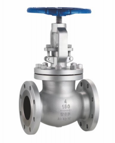
J41H/Y Drawing of national standard flange globe valve

J41H/Y National standard flange stop valve PN1.6MPa main connecting dimensions
| DN(mm) | L | D | D1 | D2 | b | f | Z-Φd | H | D0 | WT(kg) |
| 10 | 130 | 90 | 60 | 40 | 16 | 2 | 4-Φ14 | 198 | 120 | 4.7 |
| 15 | 130 | 95 | 65 | 45 | 16 | 2 | 4-Φ14 | 218 | 120 | 5.2 |
| 20 | 150 | 105 | 75 | 58 | 18 | 2 | 4-Φ14 | 258 | 140 | 7.1 |
| 25 | 160 | 115 | 85 | 68 | 18 | 2 | 4-Φ14 | 275 | 160 | 7.4 |
| 32 | 180 | 140 | 100 | 78 | 18 | 2 | 4-Φ18 | 280 | 180 | 8.5 |
| 40 | 200 | 150 | 110 | 88 | 18 | 3 | 4-Φ18 | 330 | 200 | 12.5 |
| 50 | 230 | 165 | 125 | 102 | 18 | 3 | 4-Φ18 | 350 | 240 | 20 |
| 65 | 290 | 185 | 145 | 122 | 18 | 3 | 8-Φ18 | 355 | 280 | 25 |
| 80 | 310 | 200 | 160 | 138 | 20 | 3 | 8-Φ18 | 400 | 280 | 35 |
| 100 | 350 | 220 | 180 | 158 | 20 | 3 | 8-Φ18 | 415 | 320 | 50 |
| 125 | 400 | 250 | 210 | 188 | 22 | 3 | 8-Φ18 | 460 | 360 | 75 |
| 150 | 480 | 285 | 240 | 212 | 22 | 3 | 8-Φ22 | 510 | 400 | 100 |
| 200 | 600 | 340 | 295 | 268 | 24 | 3 | 12-Φ22 | 710 | 400 | 210 |
| 250 | 730 | 405 | 355 | 320 | 26 | 3 | 12-Φ26 | 789 | 450 | 446 |
| 300 | 850 | 460 | 410 | 378 | 28 | 4 | 12-Φ26 | 925 | 500 | 648 |
J41H/Y National standard flange type stop valve PN2.5MPa main connection dimensions
| DN(mm) | L | D | D1 | D2 | b | f | Z-Φd | H | D0 | WT(kg) |
| 10 | 130 | 90 | 60 | 40 | 16 | 2 | 4-Φ14 | 198 | 120 | 4.9 |
| 15 | 130 | 95 | 65 | 45 | 16 | 2 | 4-Φ14 | 218 | 120 | 5.4 |
| 20 | 150 | 105 | 75 | 58 | 18 | 2 | 4-Φ14 | 258 | 140 | 7 |
| 25 | 160 | 115 | 85 | 68 | 18 | 2 | 4-Φ14 | 275 | 160 | 7.4 |
| 32 | 180 | 140 | 100 | 78 | 18 | 2 | 4-Φ18 | 280 | 180 | 8.5 |
| 40 | 200 | 150 | 110 | 88 | 18 | 3 | 4-Φ18 | 330 | 200 | 12.5 |
| 50 | 230 | 165 | 125 | 102 | 20 | 3 | 4-Φ18 | 350 | 240 | 16 |
| 65 | 290 | 185 | 145 | 122 | 22 | 3 | 8-Φ18 | 400 | 280 | 25 |
| 80 | 310 | 200 | 160 | 138 | 24 | 3 | 8-Φ18 | 355 | 280 | 30 |
| 100 | 350 | 235 | 190 | 162 | 24 | 3 | 8-Φ22 | 415 | 320 | 34.5 |
| 125 | 400 | 270 | 220 | 188 | 26 | 3 | 8-Φ26 | 460 | 360 | 89 |
| 150 | 480 | 300 | 250 | 218 | 28 | 3 | 8-Φ26 | 510 | 400 | 98 |
| 200 | 600 | 360 | 310 | 278 | 30 | 3 | 12-Φ26 | 710 | 400 | 180 |
| 250 | 730 | 425 | 370 | 335 | 32 | 3 | 12-Φ30 | 789 | 450 | 446 |
| 300 | 850 | 485 | 430 | 395 | 34 | 4 | 16-Φ30 | 925 | 500 | 654 |
J41H/Y Main dimensions of PN4.0MPa flange stop valve
| DN(mm) | L | D | D1 | D2 | b | f | f2 | Z-Φd | H | D0 | WT(kg) |
| 10 | 130 | 90 | 60 | 40 | 16 | 2 | 4 | 4-Φ14 | 198 | 120 | 4.9 |
| 15 | 13 | 95 | 65 | 45 | 16 | 2 | 4 | 4-Φ14 | 238 | 120 | 5.4 |
| 20 | 150 | 105 | 75 | 58 | 18 | 2 | 4 | 4-Φ14 | 275 | 140 | 7 |
| 25 | 160 | 115 | 85 | 68 | 18 | 2 | 4 | 4-Φ14 | 285 | 160 | 8.8 |
| 32 | 180 | 140 | 100 | 78 | 18 | 2 | 4 | 4-Φ18 | 302 | 180 | 11.8 |
| 40 | 200 | 150 | 110 | 88 | 18 | 3 | 4 | 4-Φ18 | 355 | 200 | 16.5 |
| 50 | 230 | 165 | 125 | 102 | 20 | 3 | 4 | 4-Φ18 | 370 | 240 | 24 |
| 65 | 290 | 185 | 145 | 122 | 22 | 3 | 4 | 8-Φ18 | 408 | 280 | 33 |
| 80 | 310 | 200 | 160 | 138 | 24 | 3 | 4 | 8-Φ18 | 436 | 320 | 44 |
| 100 | 350 | 235 | 190 | 162 | 24 | 3 | 4.5 | 8-Φ22 | 480 | 360 | 60 |
| 125 | 400 | 270 | 220 | 188 | 26 | 3 | 4.5 | 8-Φ26 | 558 | 400 | 89 |
| 150 | 480 | 300 | 250 | 218 | 28 | 3 | 4.5 | 8-Φ26 | 611 | 400 | 98 |
| 200 | 600 | 375 | 320 | 285 | 34 | 3 | 4.5 | 12-Φ30 | 720 | 400 | 190 |