
The general layout of commonly used valves requires common valves in the air conditioning water system
General layout requirements: 1. The valve should be set in a place that is easy to access and easy to operate and maintain. Valves on a row of pipes should be centrally arranged. Pipeline valves below ground level shall be located in valve Wells. 2. The center of the valve handwheel on the riser is generally 1.2m away from the operating surface, and should not exceed 1.8m
General layout requirements:
1. The valve should be located in a place that is easy to access and easy to operate and maintain. Valves on a row of pipes should be centrally arranged. Pipeline valves below ground level shall be located in valve Wells.
2. The center of the valve handwheel on the riser is generally 1.2m away from the operating surface, and should not exceed 1.8m.
3. For the valve on the horizontal pipe, the valve stem direction can be determined in the following order: vertical upward, horizontal and downward tilt 45 degrees, vertical downward is not allowed.
4. The center of the valve arranged around the operating platform should not be more than 450mm from the edge of the operating platform.
5. The horizontal installation of the open rod type valve, when the valve is opened, shall not affect the passage.
6. Parallel layout of the pipeline on the valve, the center line should be as far as possible, the net distance between the handwheel should not be less than 100mm, can be staggered layout.
7. The valve on the bottom pipe of the tower, reactor, vertical vessel and other equipment shall not be arranged in the skirt. 8. The valve should be installed as close as possible to the dry pipe or equipment, and the valve connected to the pipe mouth of the equipment should be directly connected, and the valve on the pipe connected to the highly toxic medium equipment should be directly connected to the pipe mouth of the equipment.
9. For the horizontal branch pipe led from the dry pipe, a cut-off valve should be set in the horizontal pipe section near the root.
Common valve layout requirements
1 stop valve
A Handwheel and handle operated globe valves can be installed anywhere in the pipeline
B Handwheel, handle and valve transmission mechanism are not allowed to be used for lifting
C When installed, the flow of the medium should be consistent with the direction indicated by the arrow on the valve body
If D is less than or equal to DN100, the design is generally based on low input and high output. If D is greater than or equal to DN125, the design is generally based on high input and low output
E Straight-through globe valves are installed in horizontal pipelines
2. The gate
A Manual single gate valve can be installed at any position.
B Double gate valves shall be installed upright, i.e. stem in vertical position with handwheel on top.
3. The throttle valve
A As the throttle valve is operated frequently, it should be installed in a convenient position, either in horizontal or vertical pipelines
4. Check valve
A straight through lift check valve should be installed in the horizontal pipeline; Vertical lift check valves and bottom valves are installed in vertical pipelines, and the medium flows from bottom to top.
B Check VALVES SHOULD NOT BE LOCATED DIRECTLY downstream OF PIPE bends or ELBOWS to avoid eddy CURRENTS FROM media FLOWING THROUGH them
C SWING CHECK VALVES ARE INSTALLED IN UNRESTRICTED POSITIONS, USUALLY IN HORIZONTAL PIPELINES, BUT CAN ALSO BE INSTALLED IN VERTICAL OR INCLINED pipelines.
D The bottom valve should be installed at the bottom of the water pump suction pipe
E During the design process, the damage to the valve, piping or equipment caused by the water hammer pressure when the valve is closed should be considered.
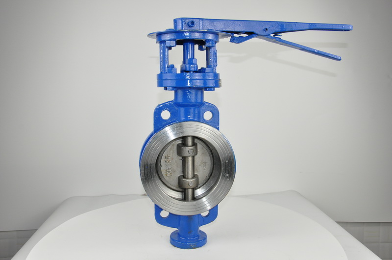
5. Butterfly valve
A Butterfly valve with spanner can be installed anywhere in pipe or equipment.
B Butterfly valve with transmission mechanism should be installed vertically or according to the product instructions
6. Ball valve
A Ball valve with wrench operation can be installed anywhere in the pipe or equipment
7. The diaphragm valve
A Diaphragm valve is not suitable for vacuum pipes and equipment
B Diaphragm valve with handwheel can be installed anywhere in the pipe or equipment
8. The relief valve
A Requirements for inlet pipe layout
* The safety valve shall be installed in a vertical upward position. Otherwise, the consent of the manufacturer should be obtained.
* Safety valves should be installed as close as possible to the equipment or system being protected.
* The inlet pipe for installing the safety valve should be short and straight. The minimum cross-sectional area of the inlet pipe shall not be less than the cross-sectional area of the inlet of the safety valve. For high pressure and large displacement occasions, the inlet pipe at the entrance should be large enough rounded radius; Or it has a tapered channel whose entrance cross-sectional area is approximately twice the exit cross-sectional area.
* When the relief valve is discharged, the pressure drop in the inlet pipe, that is, between the protected equipment and the relief valve, should be as small as possible. In no CASE SHALL THE PRESSURE DROP EXCEED 3% OF the SETTING PRESSURE OR 1/3 OF THE GREATER ALLOWABLE opening/CLOSING PRESSURE difference, whichever IS LESS. If the pressure drops too much, the relief valve frequency will jump.
* The inlet pipe is generally provided with a CB bracket
* When the isolation valve is installed at the safety valve inlet, it should not violate the relevant provisions of laws or specifications.
* The safety valve should not be installed at the dead end of the long horizontal pipe section, so as to avoid accumulation of solid or liquid materials at the dead end, affecting the normal operation of the safety valve
B Discharge pipe layout requirements
* The cross-sectional area of the discharge pipe shall not be less than the cross-sectional area of the safety valve outlet. When MULTIPLE RELIEF VALVES DISCHARGE INTO A MAIN LINE, THE CROSS-SECTIONAL AREA OF THE DISCHARGE LINE SHALL BE SUCH THAT THE TOTAL DISCHARGE FROM ALL RELIEF VALVES THAT MAY DISCHARGE INTO IT SIMULTANEOUSLY IS ACCEPTABLE.
* The discharge pipe is generally equipped with GL bracket
* Any conditions that could lead to obstruction of the discharge line should be prevented. If necessary, a drain hole should be provided to prevent rain, snow, condensate, etc. from accumulating in the drain pipe.
* The discharge and drain of the safety valve should be guided to a safe place. Special attention should be paid to the discharge and thinning of dangerous media.
* When the isolation valve is installed at the outlet of the safety valve, it should not violate the relevant provisions of laws or specifications.
9. Pressure reducing valve
A Pressure reducing valve should not be set close to rotating equipment or easy to be affected, and should be considered to facilitate maintenance
B Pressure reducing valve should be installed on the horizontal pipeline
C The outlet of the pressure reducing valve should be provided with a reliable support to avoid vibration damage during decompression
Common valves in air conditioning water system common valves in air conditioning water system are butterfly valve, check valve, globe valve, ball valve, etc., the specific use of which valve, we need to first understand the central air conditioning water system. The water system of central air conditioning system includes cooling water system and chilled water/hot water system (generally single pipe, circulating frozen water in summer and hot water in winter). Air cooled or air cooled and heated pump type includes refrigerated/hot water system only.
Air conditioning water system commonly used valves are butterfly valve, check valve, globe valve, ball valve, etc., the specific use of which valve, we need to first understand the central air conditioning water system.
The water system of central air conditioning system includes cooling water system and chilled water/hot water system (generally single pipe, circulating frozen water in summer and hot water in winter). Air cooled or air cooled and heated pump type includes refrigerated/hot water system only. Circulating water system is an important part of central air conditioning system.
A typical central air-conditioning unit is mainly composed of three parts: chilled water circulation system, cooling water circulation system and main engine:
Chilled water circulation system
This part is composed of chilled pump, indoor fan and chilled water pipe. The low-temperature chilled water flowing from the evaporator of the host machine is pressurized into the chilled water pipe (outlet water) by the refrigerant pump, enters the room for heat exchange, takes away the heat in the room, and returns to the evaporator of the host machine (return water). The indoor fan is used to blow air through the chilled water pipe to reduce the air temperature and speed up indoor heat exchange.
Cooling water circulation section
This part is composed of cooling pump, cooling water pipe, cooling water tower, etc. Chilled water circulation system for indoor heat exchange at the same time, will take away a lot of indoor heat. The heat energy is transferred to the cooling water through the refrigerant in the main engine, so that the temperature of the cooling water rises. The cooling pump will heat up the cooling water pressure into the cooling water tower (water), so that it can exchange heat with the atmosphere, reduce the temperature and then return to the main engine condenser (return water).
The host
The main engine is composed of a compressor, evaporator, condenser and refrigerant (refrigerant). Its working cycle is as follows:
First, the low-pressure gaseous refrigerant is pressurized by the compressor into the condenser and gradually condensed into a high-pressure liquid. In the process of condensation, the refrigerant will release a lot of heat energy, which is absorbed by the cooling water in the condenser and sent to the outdoor cooling tower, and eventually released into the atmosphere. Then when the high pressure liquid refrigerant in the condenser flows through the throttling and step-down device before the evaporator, it is vaporized because of the sudden change of pressure, forming a gas-liquid mixture and entering the evaporator. The refrigerant is constantly vaporized in the evaporator, and it will absorb the heat of the frozen water to make the frozen water reach a lower temperature. ***, the refrigerant in the evaporator after gasification becomes a low-pressure gas, re-enters the compressor, and so on.
The control valve used in the air conditioning water system is also known as the regulating valve, is in the pipeline system to adjust the liquid or gas flow control device. This adjustment is accomplished by changing the opening of the control valves connected in series to the piping system, thereby changing the fluid resistance.
The choice of control valve is of great significance to improve the stability of the system, prolong the service life of the control valve and save energy. Without the proper valve diameter, an automatically controlled variable water flow system will not operate at an effective level. Too large valve diameter will lead to bad control performance, may make the system shock or oscillation, and waste investment; Too small a valve diameter will require the system to provide a large pressure difference to maintain sufficient flow, so that the pump load heavier, while the valve is vulnerable to damage, and may not give the required capacity; Both will bring maintenance inconvenience and shorten the service life of the control valve.
From the above introduction, it can be concluded that the commonly used valves in the air conditioning water system are: manual butterfly valve, electric butterfly valve, anti-condensation butterfly valve, butterfly check valve, water level control valve, cut-off valve, etc. In addition, also need rubber soft connection, filter and other pipe accessories.
Post time: Sep-01-2022


