
The general regulation of valve setting requires the method of valve model preparation
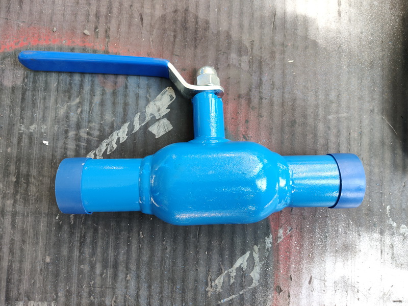
This regulation applies to the setting of gate valve, globe valve, ball valve, butterfly valve and pressure reducing valve in petrochemical plant. Check valve, safety valve, regulating valve, trap set up see the relevant regulations. This regulation does not apply to the setting of valves on underground water supply and drainage pipes.
This regulation applies to the setting of gate valve, globe valve, ball valve, butterfly valve and pressure reducing valve in petrochemical plant. Check valve, safety valve, regulating valve, trap set up see the relevant regulations. This regulation does not apply to the setting of valves on underground water supply and drainage pipes.
1 Valve layout principle
1.1 Valves should be in accordance with pipeline and instrument flow chart (P>
1.2 The valve shall be arranged in a place that is easily accessible, easy to operate and maintain. Valves on a row of pipes should be centrally arranged, and an operating platform or ladder should be considered.
Valve installation position requirements
2.1 When the pipe corridor pipelines entering and leaving the device are connected with the main pipes on the pipe corridor of the whole factory, the valve for cutting off shall be set. The installation position of the valve should be centrally arranged on one side of the device area, and the necessary operation platform or maintenance platform should be set up.
2.2 Valves that require frequent operation, maintenance and replacement should be located in a place easily accessible to the ground, platform or ladder. Pneumatic and electric valves should also be arranged in easy access.
2.3 Valves that do not require frequent operation (only used when opening or stopping) should also be placed where temporary ladders can be erected if they cannot be operated on the ground.
2.4 The height between the center of the valve handwheel and the operating surface is 750 ~ 1500mm, and the optimum height is
1200mm, valve mounts up to 1500 ~ 1800mm without frequent operation. When the installation height cannot be reduced and frequent operation is required, the operation platform or step should be set during the design. Valves on pipes and equipment with dangerous media shall not be set within the height of a person’s head.
2.5 When the center of the valve handwheel is higher than 1800mm from the operating surface, it is advisable to set the sprocket operation. The chain of the sprocket should be about 800mm from the ground, and the sprocket hook should be set, and the lower end of the chain should be hung on the wall or column nearby, so as not to affect the passage
2.6 For the valve set in the groove, when the groove cover can be operated by opening the groove, the handwheel of the valve should not be 300mm below the groove cover. When it is below 300mm, the valve extension rod should be set so that the handwheel is within 100mm below the groove cover.
2.7 When the valve set in the pipe trench needs to be operated on the ground or installed under the floor (platform) of the previous floor, the valve extension rod can be set to extend to the cover plate of the trench, floor and platform for operation. The operating surface of the hand-wheel distance of the extension rod is 1200mm. Valves WITH NOMINAL DIAMETERS OF DN40 OR LESS AND THREADED CONNECTIONS SHOULD NOT BE OPERATED WITH SPROCKETS OR EXTENSION RODS TO AVOID DAMAGING THE VALVE. In general, the valve should be operated as little as possible with sprockets or extension rods.
2.8 The distance between the edge of valve handwheel anomaly platform arranged around the platform should not be greater than 450mm. When the valve stem and handwheel extend into the upper part of the platform and the height is less than 2000mm, ensure that the stem and handwheel do not affect the operation and passage of the operator to avoid personal injury.
3. Setting requirements for large valves
3.1 Large valves should be operated with gear transmission mechanism, and the required space position of the transmission mechanism should be considered when setting. In general, VALVE SIZES larger than the following classes SHOULD be considered for USE with geared mechanisms.
3.2 Large valves shall be provided with a support on one or both sides of the valve, which shall not be located on the short pipe that needs to be removed during maintenance, and shall not affect the support of the pipeline when removing the valve. Generally, the distance between support and valve flange should be greater than 300mm.
3.3 The installation position of large valves shall have the site where cranes are used, or davits and beams shall be considered.
4. Setting requirements for valves on horizontal pipelines
4.1 Except for special requirements of the process, the handwheel of the valve installed on the general horizontal pipeline shall not face down, especially the valve on the pipeline with dangerous medium shall not face down. The orientation of the valve handwheel is determined in the following order: vertical upward; Level; Vertical upward left and right tilt 45��; Vertical downward left and right tilt 45��; Don’t go straight down.
4.2 Horizontal installation of open rod type valve, when the valve is opened, the stem shall not affect the flow, especially when the stem is located in the head or knee of the operator.
Other requirements for valve setting
5.1 The center lines of valves on parallel pipelines should be aligned as far as possible. When valves are arranged adjacent to each other, the net distance between handwheels should not be less than 100mm; Valves can also be staggered to reduce pipe spacing.
5.2 When the nominal diameter, nominal pressure and sealing surface type of the valve that is required to be connected with the pipe opening of the equipment are the same or match with the flange of the pipe opening of the equipment, it shall be directly connected with the pipe opening of the equipment. When THE VALVE IS CONCAVE flanged, ASK THE equipment professional TO provide convex FLanges at the corresponding nozzle.
5.3 Except for special requirements of the process, valves on the bottom pipes of the tower, reactor, vertical vessel and other equipment shall not be arranged in the skirt.
5.4 When the branch pipe is led out from the main pipe, the cut-off valve should be located in the horizontal section of the branch pipe near the root of the main pipe, so that the fluid can be discharged to both sides of the valve.
5.5 Branch pipe shut-off valve on pipe gallery is not operated frequently (* for parking maintenance). If no permanent ladder is set up, space for temporary ladder should be considered.
5.6 When the high-pressure valve is opened, the starting force is large. It is necessary to set the support to support the valve and reduce the starting stress. The installation height is 500 ~ 1200mm.
5.7 The fire water valve and fire steam valve in the device boundary area shall be scattered and arranged in a safe area accessible to operators in case of an accident.
5.8 The valve set of the fire extinguishing steam distribution pipe of the heating furnace should be easy to operate, and the distance between the distribution pipe and the furnace body should not be less than 7.5m.
5.9 When threaded valves are installed on pipes, a live connector must be installed near the valve for removal.
5.10 The sandwich valve or butterfly valve shall not be directly connected with the flange of other valves and pipe fittings, and a section shall be added in the middle
A short pipe with flanges at both ends.
5.11 The valve should not bear applied load to avoid excessive stress damage to the valve.
Valve model preparation method
Valve model preparation method:
Nowadays, more and more types of valve and materials, the preparation method of valve model is also more and more complex, the valve model should usually represent the valve type, drive mode, connection form, structural characteristics, nominal pressure, sealing surface material, valve body material and other elements. The standardization of valve model provides convenience for the design, selection and distribution of valves. Although our country has the valve model establishment method have uniform standard, but gradually cannot meet the needs of the development of the valve industry, at present, the valve manufacturers generally use their own number method, unified numbering method will not be used, the following table I company for the majority of users to develop a complete version of the valve figure number method, for your reference, If you have any questions, please call 021-57562898 for consultation.
Valve model preparation method:
This preparation method mainly introduces the general valve model preparation, type code, drive code, connection form code, structure form code, sealing surface material code, valve body material code and pressure code representation method. This standard is applicable to the general gate valve model, globe valve model, throttle valve model, butterfly valve model, ball valve model, diaphragm valve model, plug valve model, check valve model, safety valve model, pressure reducing valve model, steam trap model, drain valve model, plunger valve model.
The Standardization Administration recently issued the “valve model preparation method”; Proposed by the China Machinery Industry Federation, in accordance with the GB/T1.1-2009 rules to draft, valve model compilation method by the National valve Standardization Technical Committee (SAC/TC188) centralized. In line with JB/T 308-2004 editing.
Valve model preparation method sequence:
“Unit – valve type” and “the second unit – drive mode] – [the third unit - connection form] – [4 units - structure �� and �� unit 5 - lining sealing surface material or material type] – > [6 units - nominal pressure code or working temperature of the working pressure code] – [7 units - the body material] – [8 units – nominal diameter ��
Additional special such as TAICHEN pinyin, short for TC
Post time: Aug-17-2022


