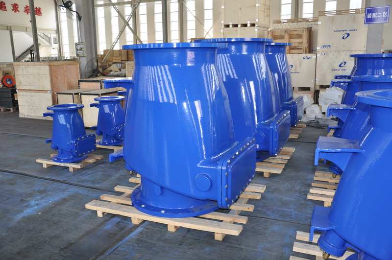
Basic valve setup comes quickly with collector valve logo and identification paint
Valve setup and selection of appropriate type (not model). Valves are an important part of the work of process system professionals when preparing PI diagrams. The content described in this regulation takes into account the general requirements of production and safety. When making engineering design by referring to these regulations, the system professional shall make a choice based on the specific situation of the project, local meteorological conditions, inter-factory cooperation, device operation requirements, fluid characteristics, special requirements of users and economy, etc. This regulation also introduces the characteristics of general industrial valves and the factors to be considered in the selection of valves in engineering design
1. The provisions are applicable to chemical process system majors. The valve mentioned does not include safety valve, steam trap, sampling valve and pressure reducing valve, but includes the flow limiting orifite plate, blind plate and other pipe fittings which have similar functions with the valve, with the cut-off valve as the general name of these valve parts. The function of the cut-off valve is used to cut off the fluid or make the fluid change the flow direction, according to the production (including normal production, open and shut down and special working conditions), maintenance and safety requirements and Settings, but also to consider the rationality of the economy.
Valve setup and selection of appropriate type (not model). Valves are an important part of the work of process system professionals when preparing PI diagrams. The content described in this regulation takes into account the general requirements of production and safety. When making engineering design by referring to these regulations, the system professional shall make a choice based on the specific situation of the project, local meteorological conditions, inter-factory cooperation, device operation requirements, fluid characteristics, special requirements of users and economy, etc.
This regulation comprehensively and generically introduces the valve setting in the listed cases and the detailed requirements of various chemical units. See the basic unit mode of the corresponding unit’s PI diagram.
This regulation also introduces the characteristics of general industrial valves and the factors to be considered in the selection of valves in engineering design.
2. Valve setting
Valve is set at the boundary
The process material and common material piping shall be cut at the plant boundary (usually inside the plant boundary area)
Valve break, except in the following cases:
(1) Exhaust system.
(2) the discharge pipe when the emergency discharge chute is located outside the boundary; If valves must be set in these two cases, lead sealing is also required to open (C.S.O)
(3) material pipe that will not cause stringing and accidents.
(4) Material tube without measurement.
FIG. 2.0.1 valve setup at boundary
Valves at the boundary are set in several ways as shown in Figure 2.0.1. Where (1) applies to general materials
Cut off; In case of safety accidents such as fire or important product quality accidents caused by material stringing, blind plates should be added in FIG. 2.0.1 to prevent internal leakage of valve. (3) and (5) in FIG. 2.0.1 are suitable for upstream or downstream line sweeping after feeding. Valve A can also be used for purging, cleaning, leak detection, or the test meter can be installed between the two valves in series. (5) in Figure 2.0.1 is applicable where pressure changes are likely to be large and the check valve acts as an instant cut-off.
Setting of root valve
When a medium needs to be transported to more than one user, in order to facilitate maintenance or energy saving, anti-freezing, in addition to the equipment attached
In addition to the cut-off valve, a cut-off valve called root valve is installed on the branch pipe close to the main pipe. Commonly used in common material systems (e.g. steam, compressed air, nitrogen, etc.). The same setting is required when a process material is used for multiple users (e.g. solvents). The valve shown in Figure 2.0.2 is the root valve. In energy-saving antifreeze requirements, the distance between the root valve and the supervisor should be as small as possible.
Figure 2.0.2 Schematic diagram of setting root valve
Root valves should be installed on all branch pipes of common material pipelines in chemical plant to avoid individual
Valve damage causes plant or plant shutdown.
Steam and overhead water piping, even to one plant or one equipment, when the branch pipe exceeds a certain length, also need to add root valve to reduce dead zone, reduce energy consumption, prevent freezing.
Two or more auxiliary steam equipment should be determined according to the importance of the production of branch pipe root valve.
The root valve of the branch pipe of common material is set by the pipeline professional in the design of pipeline layout, and the process system professional needs to check whether the branch is appropriate. And the root valve is represented on the public material PI diagram (distribution diagram).
Double valve
Liquefied petroleum gas, flammable, poisonous and precious liquids and other highly corrosive, such as strong acid, caustic soda and have special requirements (such as a stench medium caused serious pollution to the environment) medium tank, and a line at the bottom to the other devices, no matter near the other equipment for the valve and two valve should be installed in series (double valve), One of them should be snug against the tank nozzles. When the storage tank capacity is large or far away, the valve is better remote control valve. To reduce the number of valves, combine several pipes to a single opening as shown in FIG. 2.0.3–1 if operation permits.
The drain valve of the container containing the above-mentioned media shall also be double valve, as shown in Figure 2.0.3-1.
JB/T 106-2004: nominal size (DN), pressure code or working pressure code, material brand or code, manufacturer’s name or trademark, furnace number (casting valve) shall be long-term marked on the surface of pressure valve body according to GB/T 12220-1989. Valves with flow direction requirements should be marked with medium flow arrow.
One, general valve logo project
According to GB/T 12220 “General Valve Mark”, the general valve must be used and optional use of the mark items are as follows:
project
mark
project
mark
1
Nominal size (DN)
11
Standard no.
2
Nominal pressure (PN)
12
Heat number
3
Material code for pressurized parts
13
Internal material code
4
Name or trademark of manufacturer
14
Location,
5
Medium flow arrow
15
Code for lining material
6
Seal ring (gasket) code
16
Quality and test marking
7
The limit temperature
17
Inspector’s mark
8
Thread code
18
Manufacturing year, month
9
Extreme pressure
19
Flow characteristics
10
Factory No.
2. Marking methods
1. Mark content
JB/T 106-2004: nominal size (DN), pressure code or working pressure code, material brand or code, manufacturer’s name or trademark, furnace number (cast valve) shall be marked on the surface of pressure valve body according to GB/T 12220-1989. Valves with flow direction requirements should be marked with medium flow arrow.
2. Marking methods
GB/T 12220-1989: valves with nominal size greater than or equal to DN50 must be marked with nominal size (DN), nominal pressure (PN), material row or code number of pressurized parts, manufacturer’s name or trademark, melting furnace number (casting) shall be marked on the valve body. For valves with nominal size less than DN50, the above four marks shall be marked on the valve body or nameplate as specified by the designer. When the nominal pressure of the casting mark of the valve body is set below the nominal size value, the nominal pressure shall not be prefixed with the code “PN”.
GB/T 12220-1989 specifies the medium flow arrow, seal ring (pad) code only when specified in a certain valve standard must be marked on the valve body and flange respectively.
If there are no special provisions in GB/T 12220-1989, items 7 — 19 in the table above are optional signs for use on demand. Mark on valve body or nameplate as required.
GB/T 12220-1989 provides that if the handwheel size is large enough, the handwheel should be provided with an arrow indicating the direction of valve closing or additional “off” text.
JB/T 106-2004: the valve body by casting or die casting method, its logo should be cast or die cast on the valve body at the same time. When the body shape by die forging method, its logo in addition to the body at the same time die forging or die casting, can also be marked on the body by embossing method. When the shape of the valve body is processed by forging, steel pipe or steel plate rolling welding forming, its logo in addition to the formation of embossing method, but also can be used in other ways that do not affect the performance of the valve body.
Mark position and mark size
LJB /T 106-2004 regulation: marking content, should be marked on the body of easy to see parts. Markings shall be indicated as far as possible in the center cavity of the body perpendicular center line.
Post time: Jul-13-2022


