Angle type regulating valve in production is how to use? Labyrinth control valve successfully solved the problems of cavitation, noise and vibration of ordinary valves
In the automatic regulation system of the production process, the regulating valve is an important and essential link, known as the hands and feet of the production process automation, is one of the terminal control components of the automatic control system. Angular control valve flow path is simple, small resistance, generally suitable for forward use (installation). However, in the case of high pressure drop, it is recommended to reverse the use of Angle regulator, in order to improve the unbalanced force and reduce the damage to the spool, but also conducive to the flow of the medium, avoid the coking and blocking of the regulator. Angle regulating valve in reverse use, especially should avoid a long period of small opening, in order to prevent strong oscillation and damage the spool. Especially in the trial production stage of the chemical plant, due to the low load in the trial production, the design process conditions can not soon meet the requirements, the reverse use of Angle regulating valve should be as far as possible to avoid a long time of small opening, in order to prevent damage to the Angle regulating valve. In the automatic regulation system of the production process, the regulating valve is an important and essential link, known as the hands and feet of the production process automation, is one of the terminal control components of the automatic control system. It is composed of two parts: the actuator and the valve. From the point of view of hydraulics, the regulating valve is a local resistance can change the throttle element, the regulating valve is according to the input signal by changing the stroke to change the resistance coefficient, so as to achieve the purpose of regulating the flow. The structure of the angular regulating valve and the use of the structure of the 1 Angle regulating valve in addition to the valve body for the Angle, other structures are similar to the single seat valve, its characteristics determine its simple flow path, small resistance, especially conducive to the high pressure drop, high viscosity, containing suspended solids and particulate matter fluid regulation. It can avoid coking, bonding and clogging phenomenon, but also easy to clean and self-cleaning. 2 Angle type regulating valve positive and reverse use under general circumstances, Angle type regulating valve are installed in the forward, that is, the bottom into the side out. Only in the case of high pressure difference and high viscosity, easy coking, medium containing suspended particulate matter, reverse installation is recommended, that is, the material side into the bottom out. The purpose of reverse use of angular regulating valve is to improve the unbalanced force and reduce the wear on the spool, but also conducive to the flow of high viscosity, easy coking and medium containing suspended particulate matter, to avoid coking and blockage. In the acetaldehyde plant introduced by Jilin Chemical Industry Co., Ltd. from West Germany, pv-23404 Angle regulating valve is recommended for reverse use under the process condition of high pressure drop. In the water linkage test, the Angle regulating valve produces strong oscillation, and sends out harsh noise, the spool will break after the test for 4h. At that time, foreign experts believed that the spool manufacturing quality was not good. The author thinks it is not the quality problem, but due to the unreasonable use. The reasons for its fracture are analyzed below. We know that at present, except for butterfly valves and diaphragm valves which are completely symmetrical in structure, all other structure regulators are asymmetrical. When the regulating valve changes the flow direction, due to the change of flow path will cause) value change. The normal flow of all kinds of regulating valves is to make the spool open direction (positive use), the manufacturer only provides the flow capacity of the normal flow direction) value and flow characteristics. When the regulating valve is used in reverse, the flow capacity of the regulating valve will increase when the fluid flows along the direction that the spool is closed. During the water linkage test, the simulated process conditions cannot reach the normal state soon, and the regulating valve is used in the small opening state for a long time. Due to the unbalanced force, there will be serious instability. So the regulating valve will produce a strong shock and a harsh noise, resulting in the spool quickly broken. Under normal process conditions, the opening of the regulating valve is moderate, even if the small opening is short, so the regulating valve can be used normally and safely. Labyrinth control valve successfully solved the problems of cavitation, noise and vibration of ordinary valves
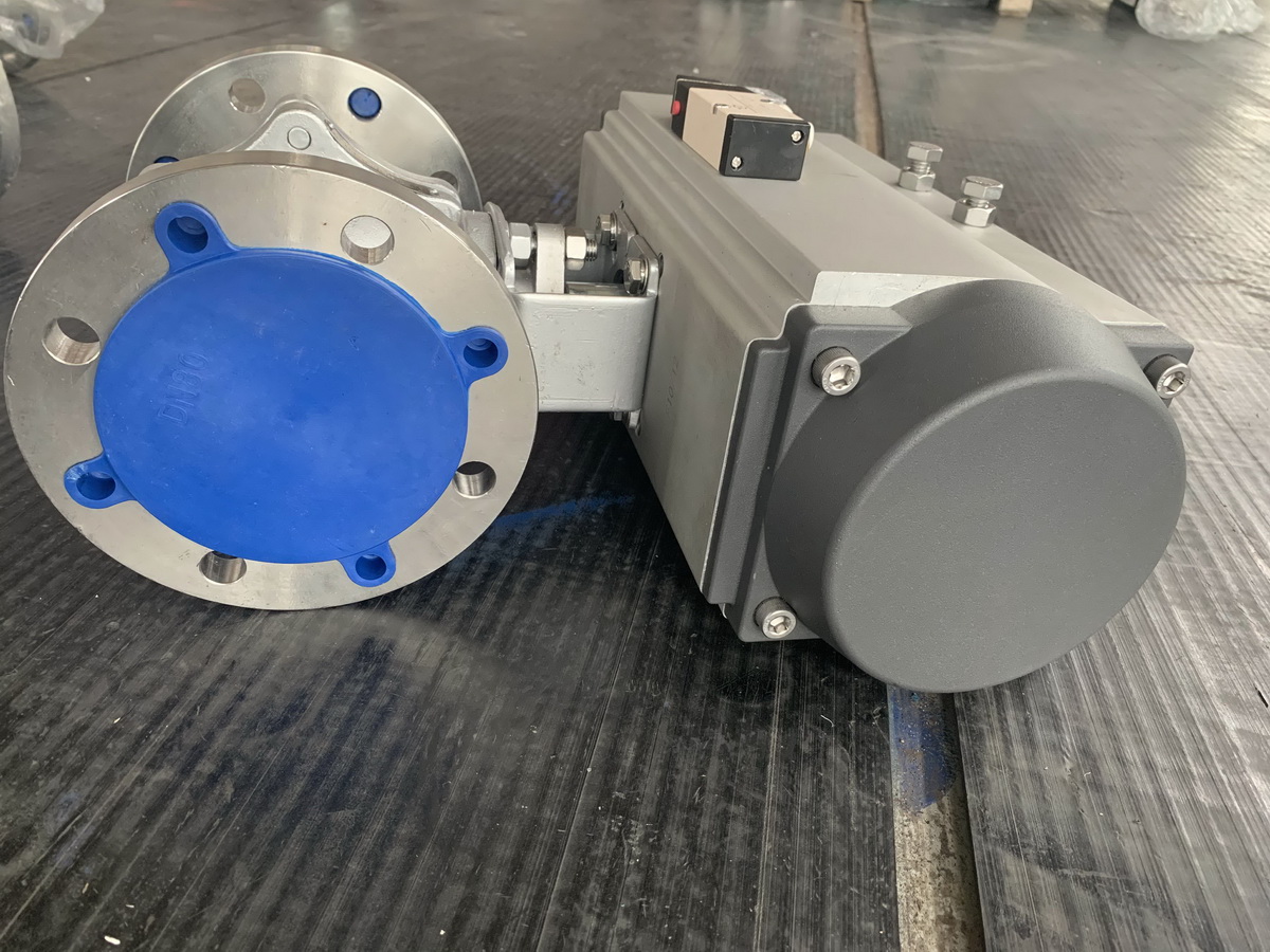
Electric or pneumatic multi-stage labyrinth regulating valve is used in the multi-stage axial flow pressure sleeve composed of labyrinth channel regulating valve, completely control the flow rate of the medium through the valve, greatly reduce the high pressure gas or steam generated in the valve noise, stable multi-level step-down effectively make the liquid does not produce cavitation, is used in the high pressure medium place stable performance control valve, Can choose multi – spring pneumatic film mechanism or electric actuator.
The labyrinth control valve consists of a cylindrical disc with a plurality of coaxial surfaces distributed with a labyrinth of curved diameters. According to the different process parameters of the medium, the design of different maze diameter specifications and the number of overlapping layers composed of the valve cage, the valve cage will be the total flow channel into many small circuiting or even step like distribution of throttling flow channel, forcing the fluid to constantly change the flow direction and flow area gradually reduce the pressure of the fluid, to prevent the occurrence of flash cavitation, prolong the service life of the valve parts. A balanced sleeve spool with a tight fit to the seat ensures extremely low leakage. The valve internals are suitable for all kinds of conditions which are easy to block the flow and cause cavitation. To the imported high pressure regulating valve brand American VTON labyrinth regulating valve as an example, generally used for high temperature and high pressure steam, as well as water supply occasions. High temperature and high pressure imported regulating valve is widely used in power station, metallurgy, petrochemical and many other industries, high temperature and high pressure regulating valve cavitation, noise and vibration problems, has been a difficult to solve the topic. Labyrinth regulating valve using mature technology, successfully solved the ordinary control valve encountered such as cavitation, high noise, vibration and other problems, has been used in the power plant boiler reduce warm water, feed pump minimum flow control and other flow regulation.
The labyrinth regulating valve can be designed specifically for the different requirements of users, through the control of the flow rate of the medium to eliminate cavitation, noise, corrosion and vibration problems. Labyrinth-type regulating valve in the structure of the design of quick disassembly, easy maintenance, can be very convenient to replace the spool; In the flow characteristics of the use of case design, so as to provide comparative flow control, with rigorous shut-off characteristics. The power plant adopts labyrinth regulating valve, which can ensure the safe and stable operation, improve the rate and prolong the maintenance cycle.
For an ordinary single-stage step-down valve, the pressure is p1 and the flow rate is v1 when the medium enters. When the medium flows to the spool part, due to the throttling effect of the spool and seat, neck shrinkage phenomenon, so the flow rate will rapidly increase to v2, and the pressure is rapidly reduced to p2, and often lower than the medium’s saturated vaporization pressure Pv. In this case, the medium vaporizes, forming bubbles. When the medium flows through the neck part formed by the valve core and seat, the working condition also changes due to the change of the channel. The pressure port rises and the kinetic energy is converted into potential energy. At this time, the pressure returns to P3 and the speed to v3. When the pressure exceeds the saturated vaporization pressure of the medium, Pv, just formed bubbles will burst, producing a strong local pressure. The huge energy when the bubble bursts can cause serious damage to the valve core, valve seat and other throttling elements in a moment, forming the so-called cavitation phenomenon. Cavitation is bound to cause valve damage, leading to leakage, serious noise and cause vibration of the valve components, thus affecting the safety and efficiency of the entire system.
Because cavitation will produce thousands of atmospheres of surface impact pressure on the throttle element, therefore, simply by improving the surface hardness of the valve core and valve seat is unable to fundamentally solve the cavitation problem. The anti-cavitation design of the labyrinth control valve is the use of the labyrinth core multistage step-down principle, by forcing the medium to flow through a series of right Angle bends so that the flow rate is completely controlled, to achieve the purpose of step-down. Regardless of the pressure drop, the resistance of these curves limits the rate at which media can flow out of the core. After multistage depressurization, the pressure of the medium is always maintained above the saturated vaporization pressure of the medium pv, thus avoiding the cavitation phenomenon and eliminating the unsafe factors. The labyrinth core pack is made of multiple labyrinth platters bonded under special conditions (using imported adhesives). Each labyrinth platter is processed with a perfect forming method to form a number of channels, and each channel can pass through a certain amount of medium, and the medium resistance is provided by a series of right Angle bends in the channel. According to the different requirements of users, through the calculation, the selection of different curve series, so that the medium speed through the labyrinth core package is always limited in a certain range. Referring to foreign mature experience, when the flow rate is less than or close to 30m/S, the impact on the throttle element erosion is minimal.
Because the flow rate and number of bends per labyrinth disc can be varied, and the disc thickness can be designed to be very thin (e.g. 2.5mm), the valve can be designed to provide flow control according to the user’s specific requirements. According to the application of the valve and user requirements, the flow characteristic curve of the regulating valve can be designed to be linear, equal percentage, modified percentage and other special curve forms. Because the working medium in the power plant valve is basically fluid (mainly water), the labyrinth inlet regulating valve generally adopts the flow close structure. When the flow close type structure, the medium into the valve body, first through the core package, then through the valve core, after the most important outflow from the valve seat, the flow of the valve is indicated by the label on the valve body.
Post time: Nov-28-2022


