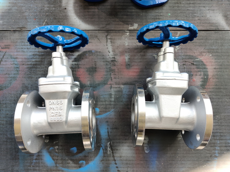
The advantages of cryogenic treatment of valves and the status quo of industrial applications

Low temperature cryogenic processing technology can significantly improve the service life of the materials are: high-speed steel, tool steel, die steel, copper electrode, powder materials, hard alloy, ceramic, etc. Examples of the use of cryogenic treatment to prolong the service life of parts by some American companies and some Chinese units are shown in Table 2 and Table 3, respectively. Table 4 shows the proportional coefficient of wear resistance change of some commonly used die materials after cryogenic treatment. Can enhance wear resistance; Enhance strength and toughness; Improve corrosion resistance, wear resistance; Enhance impact resistance; Increased fatigue strength…
Upper connection: Valve cryogenic treatment principle and its application in industry (2)
The advantages and industrial application of cryogenic treatment
3.1 Main advantages of cryogenic treatment
Can enhance wear resistance; Enhance strength and toughness; Improve corrosion resistance, wear resistance; Enhance impact resistance; Improve fatigue strength; After a cryogenic treatment, it can ensure that the treated material always has the improved mechanical properties; Does not cause the shape size deformation; Can be applied to new/used workpiece; Can eliminate internal stress; Improve material stability; The processing cost is low, because prolonging the tool life can reduce the time of tool change and grinding, so as to save the production cost; Can achieve the same surface results as other surface treatments (such as Chin plating, chrome, Teflon); Tighter molecular structures can be produced, reducing friction, heat and wear at larger contact surfaces.
3.2 The main workpiece that can be processed by cryogenic treatment
Cutting tool; Internal combustion engine parts; * * * tube; Tap; Transmission shaft; Medical instruments; Bit; The crankshaft. Agricultural machinery accessories; Milling cutter; CAM; Musical Instruments; Indexable blade; Axis; Stainless steel; Die; Gear; Nickel base alloy; Progressive die. The chain; Copper electrode material; Scissors; Shock rod; Ceramic materials; The blade; Extrusion rod; Aluminum base alloy; Get scissors; Nylon, Teflon; Powder metallurgy parts; All need in high hardness at the same time to have a relatively high degree of toughness, metal components.
3.3 Main industrial applications of cryogenic treatment
3.3.1 Extend the service life of parts and tools and improve the wear resistance
Low temperature cryogenic processing technology can significantly improve the service life of the materials are: high-speed steel, tool steel, die steel, copper electrode, powder materials, hard alloy, ceramic, etc. Examples of the use of cryogenic treatment to prolong the service life of parts by some American companies and some Chinese units are shown in Table 2 and Table 3, respectively. Table 4 shows the proportional coefficient of wear resistance change of some commonly used die materials after cryogenic treatment. As can be seen from the following three tables, cryogenic treatment produces different effects on parts and tools of different materials, and the wear resistance of parts and tools is significantly improved.
3.3.2 Improve the stability of materials
Improving the stability of materials is another successful application of cryogenic treatment in aluminum, copper, Chin and 300 series stainless steels, most notably aluminum and its alloys.
3.3.3 Improve material properties
Cryogenic treatment can enhance and improve material properties, such as strength, fatigue resistance, corrosion resistance, etc. Table 5 shows the field results obtained from the application of university research and industrial research in industrial production.
With the development of modern industry, the requirements of material properties are higher and higher. There are two major trends in contemporary materials research:
¢Ù Constantly develop new technologies, new processes and new equipment to develop a variety of new materials with special requirements or excellent properties, such as rapid solidification, mechanical alloying, jet deposition, injection molding and other processes to develop microcrystalline, amorphous, quasicrystal, nanocrystalline structural and functional materials.
¢Ú For the existing traditional materials such as iron and steel, aluminum, copper using ultra-pure purification, large deformation processing, cryotreatment and other special processing and processing technology, in the basic does not change the composition of the existing materials on the basis of greatly improve its performance, so as to effectively improve the utilization and recovery of resources. At the same time, the material properties can be improved, and the cost can be reduced to reduce the damage to the environment, which undoubtedly provides a good way to solve the increasingly serious energy and environmental problems. So the studies of materials cryogenic treatment will become an important research direction of material science workers at home and abroad, but the stability of the existing research both in cryogenic treatment process and the mechanism of action of some materials research still exist many shortcomings, for the large-scale and application of cryogenic treatment on the industrial brought obstacles, Therefore, the development and research of stable cryogenic process system and cryogenic treatment mechanism of non-ferrous metals will be the focus of the research in this field.
Valve model preparation method:
This STANDARD SPECIFIES THE REPRESENTATION METHOD OF THE MODEL NUMBER, TYPE CODE, DRIVE MODE CODE, CONNECTION FORM CODE, STRUCTURE FORM CODE, sealing surface MATERIAL CODE, VALVE body MATERIAL CODE and PRESSURE CODE for universal VALVES. This standard is applicable to the general gate valve model, globe valve model, throttle valve model, butterfly valve model, ball valve model, diaphragm valve model, plug valve model, check valve model, safety valve model, pressure reducing valve model, steam trap model, drain valve model, plunger valve model.
The Standardization Administration recently issued the “valve model preparation method”; Proposed by the China Machinery Industry Federation, in accordance with the GB/T1.1-2009 rules to draft, valve model compilation method by the National valve Standardization Technical Committee (SAC/TC188) centralized. In line with JB/T 308-2004 editing.
Valve model preparation method:
Nowadays, more and more types of valves and materials are available, and the preparation of valve models is becoming more and more complex; The valve model usually should represent the valve type, drive mode, connection form, structural characteristics, nominal pressure, sealing surface material, valve body material and other elements. The standardization of valve model provides convenience for the design, selection and distribution of valves. Although there is a unified standard of valve model preparation, it can not meet the needs of the development of valve industry gradually; At present, the valve manufacturer generally uses a unified numbering method; If the unified numbering method cannot be adopted, Taichen Company has formulated the model numbering method of ***.
Valve model preparation method sequence:
[* * * unit - valve type] – [the second unit - drive mode] – [3 units - connection form] – [the fourth unit - structure] – [5 units - lining sealing surface material or material type] – > [6 units - nominal pressure code or working temperature of the working pressure code] – [7 units - the body material] – [8 units - nominal diameter ¡¿
*** Unit: Valve Type Code:
The VALVE TYPE CODE SHALL BE EXPRESSED IN Chinese PINYIN LETTERS ACCORDING TO TABLE L. Valve Type Code Valve Type Code Ball Valve Q Blowdown Valve P Butterfly valve D Spring load relief valve A Globe valve J steam trap S gate valve Z plunger valve U check and bottom valve H plug valve X diaphragm valve G pressure reducing valve Y Throttle valve L Lever relief valve GA When THE VALVE HAS OTHER FUNCTIONS OR HAS OTHER SPECIFIC STRUCTURES, ADD A Chinese ALPHABET LETTER BEFORE THE VALVE TYPE CODE, AS SPECIFIED IN TABLE 2.
Additional models: Valves with other functions or with other specific structures are indicated in Table 2
Second function function name code second function name code insulation type B slag type P low temperature type Da fast type Q fire type F (stem seal) bellow type W slow closure type H eccentric half PQ high temperature G jacket DY A low temperature type refers to allow the use of the temperature below -46 ¡æ valve. Unit 2: Driving Mode Code:
Drive mode codes are expressed in Arabic numerals, as specified in Table 3.
Valve actuation method code Table 3
Driving Mode Code Driving Mode Code Electromagnetic driven 0 bevel gear 5 Electromagnetic -- hydraulic 1 pneumatic 6 electric -- hydraulic 2 hydraulic 7 worm gear 3 gas -- hydraulic 8 positive gear 4 electric 9 Note: Code 1, code 2 and code 8 are used when the valve is opened and closed, two power sources are required to operate the valve at the same time. Safety valve, pressure reducing valve, trap, hand wheel directly connected with the stem operation structure of the valve, this code omitted, does not indicate.
For pneumatic or hydraulic mechanism operation of the valve: normally open with 6K, 7K; The normal closed form is denoted by 6B and 7B; 3.3.4 The valve of explosion-proof electric device is represented by 9B;
Unit 3: Valve Connection Form Code:
The connection form codes are expressed in Arabic numerals, as specified in Table 4.
The specific structure of various connection forms shall be specified in standard or way (such as flange surface form and sealing way, welding form, thread form and standard, etc.), which shall not be indicated by symbol after connection code, and shall be explained in detail in the product drawing, instruction manual or order contract and other documents.
Valve connection end connection form preparation method code Table 4
Connection form CODE Connection form code Internal thread 1 pair clamp 7 EXTERNAL thread 2 clamp 8 flange type 4 sleeve 9 Welded type 6 Unit 4: Valve construction form code
Valve CONSTRUCTION FORMS ARE SHOWN IN Arabic NUMBERS AS DESCRIBED IN TABLES 5 TO 15.
Gate valve structure form code Table 5
Structure code: stem lifting type (open stem) wedge gate elastic gate 0 rigid gate single gate plate 1 dual gate plate 2 parallel gate single gate plate 3 dual gate plate 4 stem non-lifting type (dark stem) wedge gate single gate plate 5 dual gate plate 6 parallel gate single gate plate 7 pairs Gate plate 8 valve model example: Z44W-10K-100 [Z type code: gate valve] [4 connection: flange] [4 structure: open rod, parallel rigid double gate] [W sealing surface material: valve body directly processed sealing surface] [10 pressure PN1.0mpa] [K body material: malleable iron] [100 diameter: DN100mm ¡¿
Globe, throttle and plunger valves are listed in Table 6
Structure Type Code Structure Type Code Disc unbalanced straight through port 1 Disc balanced straight through port 6 Z-shaped port 2 Angle port 7 three-way port 3 -- Angle port 4 -- DC port 5 -- Trisen globe valve Model Example: J41H-16C-80 Stop valve [4 connection: flange] [1 structure: straight passage] [H sealing surface material: CR13 stainless steel] [16 pressure PN1.6mpa] [C body material: carbon steel] [80 diameter: DN80mm]
Ball valve structure form code Table 7
Structure Type Code Structure Type Code Floating ball straight channel 1 fixed ball straight channel 7 Y-shaped tee channel 2 four-way channel 6 L-shaped tee channel 4 T-shaped tee channel 8 T-shaped tee channel 5 L-shaped tee channel 9 — hemisphere straight channel 0 Q41f-16p-20 [Q type ** : ball valve] [4 Connection: flange]
Post time: Aug-16-2022


