
Pipeline valve acceptance, pressure test, Installation and matters needing attention What should be paid attention to when the pipeline valve is installed?
In fluid piping systems, valves are control elements whose main role is to isolate equipment and piping systems, regulate flow, prevent backflow, regulate and discharge pressure. It can be used to control the flow of air, water, steam, all kinds of corrosive media, mud, oil, liquid metal and radioactive media. Because the piping system to choose the most suitable valve is very important, so, to understand the characteristics of the valve and the selection of the valve steps and basis also become crucial.
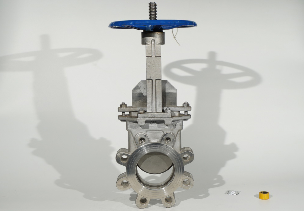
The valves
In fluid piping systems, valves are control elements whose main role is to isolate equipment and piping systems, regulate flow, prevent backflow, regulate and discharge pressure. It can be used to control the flow of air, water, steam, all kinds of corrosive media, mud, oil, liquid metal and radioactive media. Because the piping system to choose the most suitable valve is very important, so, to understand the characteristics of the valve and the selection of the valve steps and basis also become crucial.
The 4 functions of the pipeline valve
First, cut off and release medium
This is the basic function of the valve, usually choose a straight passage valve, its flow resistance is small.
Downward closed valve (globe valve, plunger valve) because of its tortuous flow path, flow resistance is higher than other valves, so less selected. Closed valves may be used where high flow resistance is permitted.
Two, control the flow
A valve that is easy to adjust is usually chosen to control flow. Downward CLOSING valves (such AS GLOBE valves) ARE SUITABLE FOR THIS PURPOSE BECAUSE THE SEAT size IS PROPORTIONAL TO THE STROKE OF THE SHUTOFF.
Rotary VALVES (PLUG, butterfly, BALL valves) and FLEXURE BODY VALVES (PINCH, DIAPHRAGM) ARE ALSO AVAILABLE FOR THROTTLING CONTROL, but USUALLY ONLY IN a limited range of valve DIAMETERS.
Gate VALVE IS A disc shaped gate to the circular seat port to do transverse motion, it only in close to the closed position, can better control the flow, so usually not used for flow control.
Three, commutation shunt
The valve may have three or more channels, depending on the need for reversing and diverting. Plug and ball valves are more suitable for this purpose, and therefore, most valves used for reversing and diverting are selected as one of these valves.
However, IN SOME CASES, other TYPES OF VALVES MAY ALSO BE USED AS commutATION diverTERS, PROVIDED THAT TWO or MORE VALVES ARE properly connected to EACH other.
4. Medium with suspended particles
When the medium with suspended particles, ** suitable for the use of the closing parts along the sealing surface of the sliding valve with wiping action.
If THE SHUTOFF IS VERTICAL TO THE BACK AND FORTH MOVEMENT OF THE SEAT, PARTICLES MAY BE TRAPPED, SO THIS VALVE IS ONLY SUITABLE FOR BASICALLY CLEAN MEDIA UNLESS THE SEALING MATERIAL ALLOWS FOR PARTICLES TO BE EMBEDDED. Ball valves and plug valves wipe the sealing surface during opening and closing, so they are suitable for use in media with suspended particles.
Pipeline valve as an important part of the process system. The installation quality of pipeline valve directly determines the good realization of related functions of process system. The main control links of its management are as follows:
1, valve inspection and acceptance
1.1 Inspection of valve appearance: no pores, trachoma, cracks and rust in valve body; Stem no bending, corrosion phenomenon, stem thread is smooth, neat without broken wire; Gland with good, flexible rotation of the handwheel; Flange sealing surface without scratches, pockmarks, etc.; Thread connection in good condition; Qualified welding groove. Valve bit number, pressure and other parameters are consistent with the design.
1.2 Document inspection: Documents mainly include: quality plan, material proof, as-built drawings, test records, maintenance manuals, storage requirements, and certificate of conformity. Non-conforming valves shall have corresponding conditional release documents and entity non-conforming identification plates.
2. Valve storage and maintenance requirements
Keep valve inlet and outlet closed and place desiccant, replace regularly according to desiccant instructions. Determine temperature, humidity and environmental requirements for storage according to valve maintenance documents. For stainless steel valves, be careful to select non-halogen wrapping material. Valves should be checked and maintained regularly during storage.
3, valve pressure test
Because the valve has been done shell, seat and closing pressure test before leaving the factory, only do the closing test of the valve on site. For the scope and proportion of the verification, the national standard GB50184-2011 describes the proportion of the field pressure test, foreign standards have no requirements. Usually the owner is determined according to the quality supervision and use experience of the valve manufacturing stage, and the general valve needs to be 100% closed in the field.
3.1 Test medium requirements: the valve test medium is water; Use different levels of water quality according to the cleanliness of the system; However, when the valve working medium is gas, the test medium is preferred to use dry oil-free compressed air or nitrogen, and can also be replaced by water pressure.
3.2 Determination of closing test pressure: The requirements for closing test pressure of valves in the GB/T13927-2008 and ASME B16.34 and MSS-SP-61 are basically the same. The HYDROSTATIC TEST PRESSURE IS 1.1 TIMES THE RATED PRESSURE FOR THE VALVE PRESSURE CLASS AT 100OF, OR A PRESSURE TEST OF LESS THAN 80psi MAY BE USED INSTEAD. When THE VALVE NAMEplate IS MARKED WITH a LARGE WORKING PRESSURE difference OR THE OPERATING mechanism of the valve is not suitable for high-pressure sealing pressure test, THE test pressure can be carried OUT according to 1.1 times of THE larger working pressure difference marked with the valve nameplate.
3.3 Evaluation of test results: The valve closing test specification only requires the test to last for the shortest time, and there is no special requirement to close the test for no less than 5 minutes in actual operation. The valve sealed with flexible material shall have no visible leakage and no pressure drop of the pressure gauge during the pressure holding time. For PARTS OF THE VALVE DESIGN THAT ALLOW LEAKAGE, USSS MAY DIRECTLY MEASURE LEAKAGE PER UNIT TIME OR USE THE NUMBER OF BUBBLES OR WATER DROPLETS AS DESCRIBED IN THE MSS-SP-61 PRESSURE TEST. Leakage IS related to the nominal diameter of the valve. The leakage requirement of national standard is similar to that of American standard.
4. Valve installation
4.1 Information check before installation: Verify the bit number, system number, type, pressure level and other information on the item entity according to the valve information in the drawings and design change documents of ***, and verify whether the installation space and subsequent maintenance space are sufficient. Valve operation is accessible.
4.2 Valve protection: For vulnerable parts of the valve, disassembly or hard protection can be carried out before installation. Piping AND EQUIPMENT FOR VALVE INSTALLATION SHOULD BE PURGED IN ADVANCE TO CONFIRM THE INTERNAL CLEANLINESS TO PREVENT DEBRIS IN PIPING AND EQUIPMENT FROM DESTROYING THE sealing surface OF THE VALVE.
4.3 Installation direction: The flow direction marked on the valve body should be consistent with the flow direction of the system medium. The safety valve must be mounted vertically. For the lift check valve, can only be installed in the horizontal pipeline should ensure that the valve disc vertical; For swing check valves, keep the pin level.
4.4 Valve installation and connection:
Weld valves: CHECK valve groove size, confirm valve material, use correct WPS. For soft seal welding valve, when welding, can remove the sealing ring after welding, welding is finished to reinstall the sealing ring; It can also be controlled by valve opening and welding temperature according to the manufacturer’s requirements. For VALVES REQUIRING heat treatment before and after welding of thick wall alloy pipes, pay attention to the allowable temperature value of the inner parts of the valve during heat treatment.
Flange valve: Check that the sealing surface of the flange is free of defects and the sealing form and pressure level of the connecting flange should be the same. It is strictly prohibited to force the group. Bolts should be freely inserted, tightened symmetrically and torque recorded. For high temperature valves over 300, heat tighten flange and packing gland bolts under hot condition.
Thread connection: considering convenient removal, it is better to set up flexible joints at both ends of the valve, pay attention to the selection of thread sealing materials, for copper, cast iron machine non-metal valves, the thread can not be screwed too tight, so as not to damage the valve.
5, valve common problems and control measures
The most common problem in field valve installation is valve leakage. The main reasons are:
1. The poor cleanliness of the pipeline causes foreign bodies stuck in the sealing surface of the valve and damages the sealing surface;
2, welding temperature control is poor, resulting in valve seal burn out deformation;
3. After the completion of the hydraulic test, the valve is not cleaned and dried in time, resulting in corrosion of the valve;
4, valve packing gland bolt is not fastened;
5, valve packing seal failure damage.
General rules for installation
1. The installation position of the valve should not interfere with the operation, disassembly and maintenance of the equipment, pipeline and valve body itself, while taking into account the appearance of the assembly.
2. For valves on horizontal pipelines, install the valve stem upward or at a certain Angle, do not install the handwheel downward. The valve, stem and handwheel on the high altitude pipe can be installed horizontally, and the opening and closing of the valve can be remotely operated by the chain in the vertical low place.
3. Symmetrical arrangement, neat and beautiful; The valve on the riser, under the premise of allowing the process, the valve handwheel to chest height ** suitable operation, generally 1.0-1.2m from the ground is appropriate, and the valve stem must be installed along the direction of the operator.
4. The center line elevation of the valves on the side-by-side riser is relatively consistent, and the net distance between the handwheels is not less than 100mm; Valves on side-by-side horizontal lines should be staggered to reduce pipe spacing.
5. When installing heavy valves on water pumps, heat exchangers and other equipment, valve supports should be set; When the valve is operated frequently and installed above 1.8m from the operating surface, a fixed operating platform should be provided.
6. If there is an arrow mark on the valve body, the arrow point is the flow direction of the medium. When installing the valve, be careful that the arrow points in the same direction as the medium in the pipeline.
7. When installing flange valves, ensure that the two flange end faces are parallel and concentric, and do not use double gaskets.
8. When installing threaded valves, a threaded valve shall be equipped with a live connection for easy disassembly. The setting of the live connection should consider the convenience of maintenance, usually the water flow through the valve and then through the live connection.
Post time: Oct-25-2022


