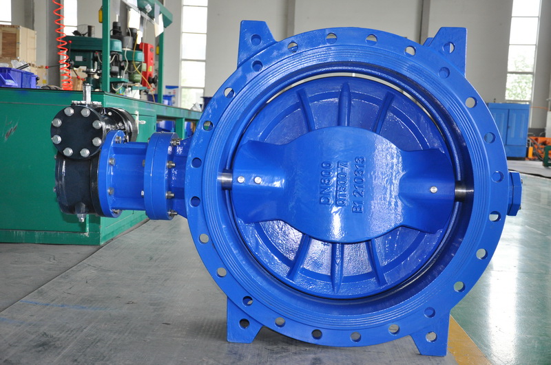
Introduction of electric actuators for power station valves (II)
The device that can control the flow of fluid in the pipeline by changing the section of the pipeline is called valve or valve part. The main role of the valve in the pipeline is: connected or truncated medium; Prevent media backflow; Adjust the pressure, flow and other parameters of the medium; Separating, mixing, or distributing media; Prevent the medium pressure exceeds the specified value, in order to keep the road or container, equipment safety.
The device that can control the flow of fluid in the pipeline by changing the section of the pipeline is called valve or valve part. The main role of the valve in the pipeline is: connected or truncated medium; Prevent media backflow; Adjust the pressure, flow and other parameters of the medium; Separating, mixing, or distributing media; Prevent the medium pressure exceeds the specified value, in order to keep the road or container, equipment safety.
With the development of modern science and technology, valve in industry, construction, agriculture, national defense, scientific research and people’s life and other aspects of use increasingly common, has become an indispensable general mechanical products in various fields of human activities.
Valves are widely used in pipeline engineering. There are many types of valves for different purposes. Especially in recent years, new structures, new materials and new uses of valves have been developed. In order to unify the manufacturing standards, but also for the correct selection and identification of the valve, in order to facilitate production, installation and replacement, valve specifications are standardization, generalization, serialization direction development.
Classification of valves:
Industrial valve was born after the invention of steam engine, in the past twenty or thirty years, due to the petroleum, chemical, power station, gold, ships, nuclear energy, aerospace and other aspects of the need, put forward higher requirements on the valve, so that people research and production of high parameters of the valve, its working temperature from the first temperature -269℃ to 1200℃, even as high as 3430℃; Working pressure from ultra-vacuum 1.33×10⁻⁸Pa(1×10¹⁰mmHg) to ultra-high pressure 1460MPa; Valve sizes range from 1mm to 6000mm and up to 9750mm. Valve materials from cast iron, carbon steel, development to titanium and titanium alloy steel, and the most corrosion resistant steel, low temperature steel and heat resistant steel valve. The driving mode of the valve from dynamic development to electric, pneumatic, hydraulic, until the program control, air, remote control, etc.. Valve processing technology from ordinary machine tools to assembly line, automatic line.
According to the role of open and close valve, valve classification methods are many, here to introduce the following several.
1. Classification by function and use
(1) stop valve: stop valve is also known as closed valve, its role is to connect or cut off the medium in the pipeline. Cut-off valves include gate valves, globe valves, plug valves, ball valves, butterfly valves and diaphragm valves.
(2) check valve: check valve, also known as check valve or check valve, its role is to prevent the medium in the pipeline flow back. Water pump suction off the bottom valve also belongs to the check valve.
(3) safety valve: the role of safety valve is to prevent the medium pressure in the pipeline or device from exceeding the specified value, so as to achieve the purpose of safety protection.
(4) regulating valve: regulating valve class including regulating valve, throttle valve and pressure reducing valve, its role is to adjust the pressure of the medium, flow and other three.
(5) shunt valve: the shunt valve category includes all kinds of distribution valves and traps, etc., its role is to distribute, separate or mix the medium in the pipeline.
2. Classification by nominal pressure
(1) Vacuum valve: refers to the valve whose working pressure is lower than standard atmospheric pressure.
(2) low pressure valve: refers to the nominal pressure PN≤ 1.6mpa valve.
(3) medium pressure valve: refers to the nominal pressure PN is 2.5, 4.0, 6.4Mpa valve.
(4) High pressure valve: refers to the valve whose pressure PN is 10 ~ 80Mpa.
(5) Ultra-high pressure valve: refers to the valve with nominal pressure PN≥100Mpa.
3. Classification by operating temperature
(1)** temperature valve: used for medium working temperature T-100 ℃ valve.
(2) low temperature valve: used for medium working temperature -100℃≤ T ≤-40℃ valve.
(3) normal temperature valve: used for medium working temperature -40℃≤ T ≤120℃ valve.
(4) medium temperature valve: used for medium working temperature of 120℃
(5) high temperature valve: used for medium working temperature T450 ℃ valve.
4. Classification by driving mode
(1) Automatic valve refers to the valve that does not need external force to drive, but relies on the energy of the medium itself to make the valve action. Such as safety valve, pressure reducing valve, trap, check valve, automatic control valve and so on.
(2) Power drive valve: power drive valve can use a variety of power sources to drive.
Electric valve: Valve driven by electricity.
Pneumatic valve: valve driven by compressed air.
Hydraulic valve: Valve driven by the pressure of a liquid such as oil.
In addition, there are several combinations of the above driving methods, such as gas-electric valves.
(3) Manual valve: manual valve with the help of hand wheel, handle, lever, sprocket, by manpower to control the valve action. When the valve opening and closing torque is large, the wheel or worm gear reducer can be set between the hand wheel and the valve stem. If necessary, universal joints and drive shafts can also be used for remote operation.
In summary, valve classification methods are many, but mainly according to its role in the pipeline classification. General valves in industrial and civil engineering can be divided into 11 categories, namely gate valve, globe valve, plug valve, ball valve, butterfly valve, diaphragm valve, check valve, throttle valve, safety valve, pressure reducing valve and trap valve. Other special valves, such as instrument valves, hydraulic control pipeline system valves, valves used in various chemical machinery and equipment, are not included in this book
(2) When the electric actuator is configured with the field position indicating mechanism, the pointer of the indicating mechanism should be consistent with the rotation direction of the switch of the output shaft, and there is no pause or hysteresis in operation. The rotation Angle range should be 80°~280° when the electric actuator is configured with the position transmitter. The voltage of the power supply should be DC 12V~-30V, and the output position signal should be (4~20) mADC, and the error of the actual displacement of the final output of the electric actuator should not be greater than 1% of the value range of the output position signal
Connecting: Introduction to electric actuators for power station valves (I)
5.10. When the electric actuator is equipped with the field position indicating mechanism, the pointer of the indicating mechanism should be consistent with the rotation direction of the switch of the output shaft, and there is no pause or hysteresis in operation. The rotation Angle should be 80°~280°
5.2.11 when the position transmitter is configured for the electric actuator, the voltage of the power supply shall be 12V~-30V, and the output position signal shall be (4~20) mADC, and the error of the actual displacement of the final output of the electric actuator shall not be greater than 1% of the range indicated by the output position signal
5.2.12 Noise of electric actuator under no load shall be measured by sound level meter not more than 75dB (A) sound pressure level
5.2.13. The insulation resistance between all current-carrying parts of the electric actuator and the housing shall be no less than 20M ω
5.2.14 The electric actuator shall be able to withstand the frequency of 50Hz, the voltage is the sinusoidal alternating current specified in Table 2, and the dielectric test lasts for lmin. During the test, insulation breakdown, surface flashover, significant increase of leakage current or sudden drop of voltage shall not occur.
Table 2 Test voltage
5.2.15 The hand-to-electric switching mechanism shall be flexible and reliable, and the handwheel shall not rotate during electric operation (except driven by friction).
5.2.16 The greater control torque of the electric actuator shall not be less than the rated torque. ** The small control torque shall not be greater than the rated torque, and shall not be greater than 50% of the relatively large control torque
5.2.17 The set torque shall not be greater than the relatively large control torque and not less than the minimum control torque. If the user does not request the torque, the minimum control torque shall be set.
5.2.18 The blocking torque of the electric actuator shall be 1.1 times greater than the larger control torque.
5.2.19 The torque control part of the electric actuator shall be sensitive and reliable, and be able to adjust the size of the output control torque. The repeat accuracy of the control torque shall conform to the provisions of Table 3.
Table 3 Control torque repetition accuracy
5.2.20. The stroke control mechanism of the electric actuator shall be sensitive and reliable, and the position repetition deviation of the control output shaft shall conform to the provisions in Table 4, and there shall be signs to adjust the position of “on” and “off”.
Table 4 Position repetition deviation
5.2.21 when the electric actuator instantaneously bears the load specified in Table 5, all bearing parts shall not be deformed or damaged.
5.2.22, switching type electric actuator shall be able to withstand the life test of continuous operation without failure for 10,000 times, and regulating type electric actuator shall be able to withstand the life test of continuous operation without failure for 200,000 times.
5.3 Technical requirements of electric actuators with power control parts
5.3.1 Electric actuators equipped with power control parts shall include proportional and integral electric actuators.
5,3.2 the electric actuator with power control part shall meet the technical requirements in 5.2.
5.3.3 The basic error of the electric actuator shall be no more than 1.0%
5.3.4 The return error of the electric actuator shall not be greater than 1.0%
Post time: Jul-26-2022


