[dry goods] power plant main valve maintenance DQW part of the rotary actuator applicable valve matters

A check valve is a valve used to prevent backflow of media in pipes and equipment. The exhaust check valve is set on each exhaust pipe of the external heater in the steam recovery system of the steam turbine set. Its function is to close the valve plate automatically when the unit is dumping load, so as to prevent the steam in the steam side of the heater and the steam inlet pipe from falling back into the steam turbine and causing the steam turbine to overspeed to avoid accidents.
Maintenance of main valves
1. Extraction check valve
A check valve is a valve used to prevent backflow of media in pipes and equipment. The exhaust check valve is set on each exhaust pipe of the external heater in the steam recovery system of the steam turbine set. Its function is to close the valve plate automatically when the unit is dumping load, so as to prevent the steam in the steam side of the heater and the steam inlet pipe from falling back into the steam turbine and causing the steam turbine to overspeed to avoid accidents.
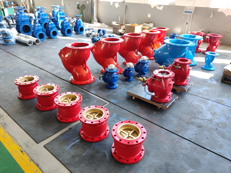
The exhaust check valve of imported 300MW unit is air-controlled swing check valve, the structure is shown in the figure, and the structure of air-controlled control seat is shown in the figure. It is mainly composed of valve body, valve plate, shaft, sleeve and so on. The air control seat is composed of piston, cylinder block, door rod and spring.
Extraction non-return valve in the closed unit startup, at all levels of heater starts, random extraction non-return valve pneumatic control of the air intake, the piston rod drives the rocker arm rotation, the check valve shaft sleeve of valve plate axis limit open, the valve plate in a free state, by extraction steam pressure to open the valve plate, the steam through the valve into the heater.
During the normal operation of the unit, the check valve plate is kept in the normally open position due to the effect of the extraction pressure. When the unit dumps the load to stop, the extraction steam pressure plummets, the valve plate depends on its own weight quickly back to the seat, the valve will be closed, so as to prevent the heater and the steam in the pipeline back to the steam turbine, to achieve the role of protection
The preparation work before the overhaul of the extraction check valve has the following contents:
After THE EQUIPMENT STOPS SERVICE, THE PROTECTION AND THE power and air sources ARE CUT off, the air inlet and outlet joints of the air control seat shall be loosened, the pins connected with the piston rod of the control seat and the check valve lever shall be removed, and the control seat shall be removed after loosening the fixing bolts of the control seat and placed quantitatively. Then, proceed to the following work.
1, valve disintegration
(1) First, mark the coordination between the cap and the valve body with a marker, and then loosen the cap bolt to remove the cap.
(2) Remove the bearing, oil retaining ring and lever on the connecting side of the lever shaft and the air control seat, and place them in a fixed position.
(3) Loosen the large seal cover nut and remove the large pressure ring.
(4) After making matching marks, loosen the fixing bolts of the large support, remove the large support, and place it.
(5) Remove the lever shaft and bushing, and place them.
(6) Remove the small bracket and accessories on the shaft side of the rocker arm and place them.
(7) Loosen the fixing nut on the small pressure ring, remove the small pressure ring, and place quantitatively.
(8) After making the matching mark, loosen the fixing bolt on the flange cover, remove the flange cover, and place it.
(9) Remove the rocker arm and spool, and place them.
(10) Take out the rocker arm and spool, and place them.
2, valve cleaning inspection
(1) Check the valve line on the spool and valve body. The valve line should have no grooves, pores and traces of the transverse sealing surface that affect the sealing performance, and should be in full contact without interruption. If the defects affecting the sealing performance are found, grinding and other treatments should be carried out.
(2) Check the connection between valve butterfly and rocker arm, adjust the gasket and rocker arm gap between 1 ~ 1.2mm, should not be too large or too small, otherwise it should be adjusted. The nut connection between the valve butterfly and rocker arm should be firm, the welding joint should be complete and crack free, and the gap between the valve butterfly shaft and rocker arm ring should meet the requirements.
(3) Check the clearance between lever shaft, rocker shaft and size bushing and cast arm should meet the requirements, and the surface of each shaft and the inner wall surface of the bushing should be smooth and clean without pits.
(4) Check the packing in the big seal cover and flange cover, should be complete, if there is damage should be replaced.
(5) Check that the sealing surface of the valve cap and valve body should be complete, without grooves, tracholes and through scratches that affect the sealing effect.
(6) Clean and check the sealing surface at the joint of the support, flange cover and valve housing, and the old gasket adhered to the sealing surface should be cleaned and shovel away. The sealing surface shall have no defects affecting the sealing effect.
(7) All keys and keyways should be cleaned and properly connected.
3, valve assembly
Before the valve is installed, the surface of each shaft and bushing should be rubbed with molybdenum disulfide powder until shiny. The assembly should be carried out according to the assembly mark in the reverse sequence of disassembly. The following points should be paid attention to in the assembly process:
(1) After the valve butterfly is connected with the rocker arm, the thickness of the adjusting gasket can be adjusted to ensure that the Angle of the valve butterfly switch reaches the Angle required by the manufacturer. After that, the tightening nut should be spot welded firmly with the valve butterfly.
(2) When the lever shaft, rocker shaft and rocker arm are assembled, the lever shaft and rocker arm end, the adjusting gasket of rocker arm shaft and rocker arm end should have a gap of 1 ~ 1.20mm.
(3) When the rocker shaft, lever shaft and the support and flange cover connected with the valve shell are installed and tightened, attention should be paid to keeping the two axes concentric to prevent the valve butterfly switch from being loose or stuck.
(4) In the process of packing at both ends, the action of each axis (lever shaft, rocker shaft) should be ensured to be flexible and not stuck.
(5) All gaskets should be updated.
4, the disintegration of the control seat
(1) the upper cover of the control seat and the cylinder block, the cylinder block and the base are assembly marks, remove the short bolts in the fastening bolts of the cylinder and the base, and place them.
(2) Loosen the nuts of the two long fastening bolts at the same time or separately, and it shall be done slowly (alternately when loosening respectively) until loosened, and the bolts shall be fixed and placed.
(3) the upper cover of the control seat, the cylinder block and the base are separated, the piston, the door rod and the spring are removed, and the position is placed.
(4) Remove the cotter pin and hexagonal groove nut, so that the piston rod and piston are separated, fixed placement.
(5) Check and clean the control seat.
1) Check that the inner wall of the piston cylinder should be smooth.
2) Check the cylindrical compression spring, and record the length of the spring in the free state, so as to compare with the previous (after) maintenance.
3) Check the piston rod and piston surface should be smooth.
4) Check the sealing surface of the upper cover, cylinder block and base connection should be intact, and clean up.
(6) Installation of the control seat. The installation and reassembly of the control seat should be carried out according to the inverse step of disassembly, and the following points should be paid attention to:
1) Each sealing O-ring is replaced with new, replace the temperature resistant rubber, type sealing ring;
2) the inner wall of the cylinder body and the surface of the piston should be coated with silicone grease to ensure lubrication;
3) After the air control seat is installed, the empty stroke of the piston rod is checked with compressed air, which should meet the requirements of the manufacturer, and the action of the piston rod should be flexible and continuous without sticking phenomenon.
(7) overall check. Fix the control seat on the valve body, and connect with the lever of the valve, connect the compressed air connector, and carry out the overall check. Requirements:
1) After assembling with the extraction check valve, the travel of the compressed air switch should conform to the travel stipulated by the manufacturer.
2) In the switching process, the overall action should be continuously flexible, without stuck phenomenon.
3) The opening indicator of the valve should be checked correctly, and the action switch should be checked together with the thermal control. The open and close display is consistent with the actual position indication of the valve, and the verification is finished.
Two, the trap valve
1, the introduction of
Steam turbine drain system is an important part of the steam turbine thermal system, especially, main steam and reheat steam turbine ontology and high pressure valves, give new steam drain pump turbine and some other important drain valve, in unit warm pipe, the normal hydrophobic requirements in a timely manner, and in the normal operation of the unit, to cut off the valve to be reliable, no leakage. If these traps leak, the impact on the efficiency of the unit is very obvious.
In view of this, the introduction of 300MW steam turbine unit of some important drain valves are imported valves, the structure of the type of gas control operation of the two-position cut-off valve. The globe valve has the advantages of simple structure, good sealing and maintenance. The globe valve is equipped with a pneumatic control mechanism, which makes the valve operate quickly and responsive, and can better meet the requirements of unit automation. The pneumatic control part is the product of the American VALTEK company, and the valve body part is the product of the American ONVAL company. The structure of the valve is shown in the figure, and the structure of the air control device is shown in the figure.
Post time: Aug-13-2022


